Introduction
With the use of Grasshopper/Extruder Turtle we developed a rudimentary slicing program to generate unique infill patterns that within models that are not implemented by CURA or Bambu Studio. With our newly developed patterns, we hope to maintain structural integrity while reducing filament quantity. To evaluate the effectiveness of our design we will conduct a tensile stress test and will be conducted with various already implemented infill patterns from CURA or Bambu Studio. The test was conducted twice in different orientations for analyzing the patterns under varying conditions. Our work results in two new infill patterns, along with a grasshopper program that can readily apply user generated infill patterns for future study.
Background Research
There has been research conducted about the tensile properties of 3D printed objects by varying the infill pattern and infill density. Many of the researchers have come to the conclusion that infill density has a direct correlation with strength. The infill pattern does influence strength, but most patterns offer comparable performance. This foundation will be valuable reference point for developing and testing our unique infill pattern. Our aim will be different since we intend to create a new infill pattern to maintain integrity while reducing filament quantity. While also researching more into have infill patterns affect structural integrity versus density.
Process
Initial Pattern Generation
To design our pattern, we began by selecting a base shape that would provide structural support while maintaining adequate spacing between elements. Insight from previous research and past coursework guided us in identifying the most suitable base shape. From this, we understand that triangles function as trusses and are commonly used in structural designs due to their strength and stability. However, since triangular infill patterns are already implemented we to find a shape that’s similar for our solution. We came to the conclusion that the isosceles trapezoid will fit the requirements we need. Sketches on different patterns using the isosceles trapezoid as the base shape were drawn as initial designs and proof of concept.
Once initial designs were formulated, ExtruderTurtle was then used to build prototypes and to determine the settings needed for the best print. During this process many challenges arise due to bed adhesion issues, z-axis inconsistencies, and extruder path. Many failed prints were produced in order to get the proper printer parameters.
Next we moved to grasshopper/rhino in order to create the same patterns but now export it as an STL file. During this we found many issues where Rhino didn’t how to interpret the shape. Since our patterns uses existing edges to build the next trapezoid, Rhino treats this edge as an interception so during extrusion there is conflicts. Secondly. due to our pattern we can’t connect the entire pattern as a single curve. We could have offset the trapezoids but that would defeat the purpose of the pattern and the reduced filament quantity.
Revised Pattern Generation and Toolpath Generation
Unable to determine a method for generating the infill within the bounds of a model using ExtruderTurtle, our focus returned to generating the infill pattern using Grasshopper. Given a single unit cell provided by the user (set of curves that can be translated on the XY plane to create a tiling), the rhinoscriptsyntax CopyObject and MoveObject methods are used to create a lattice (inspired from the Tiling project). This allows us to retrieve only the portion of the lattice inside the boundary representation of a closed curve by retrieving curve results from the CurveBrepIntersect() method. We then performed a straight extrusion of both the model curve and infill curves. Taking these results, we used the sample lecture on creating a slicer with ExtruderTurtle to slice the outer shell (the model) and the infill separately into their layers. Then, given a set of points in a layer, a single turtle uses the Euclidean set_position() method in ExtruderTurtle to generate the toolpath.
Creating the toolpath for the infill at each layer however is non-trivial, as simply collecting all points in the infill pattern and having a turtle follow each point would lead to an incorrect pattern being generated. To solve this issue, we created an adjacency-list representation of the curves within an infill layer and use a naive single-source traversal of the adjacency list to create the infill toolpath, which runs after the shell layer is printed by the turtle. A visited list is used to store edges that have already been printed, ensuring edges are not printed at a single layer more than once.
This initial approach proved to work well for models which had the same area from bottom-to-top on the z-axis. However, infill generation became unpredictable for models that did not follow this restriction. A second approach for creating the infill pattern inside of the model thus needed to be taken (the results of which can be observed in Outcome). Instead of collecting the intersecting portion of the lattice before slicing, we slice the entire extruded lattice into its layers, then find the intersection at each layer of the model. The resulting points of each curve in the intersection is then stored within a list in a dictionary, where the key is the layer that each curve belongs to. This approach allowed for our slicing program to correctly determine where the infill cuts of at each layer rather than relying on grasshopper, eliminating the issue of area changes on the z-axis.
Outcome
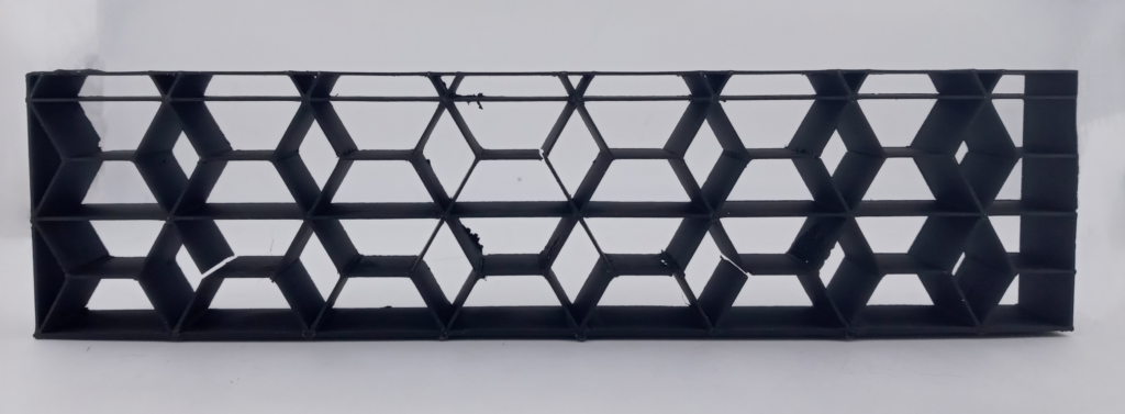
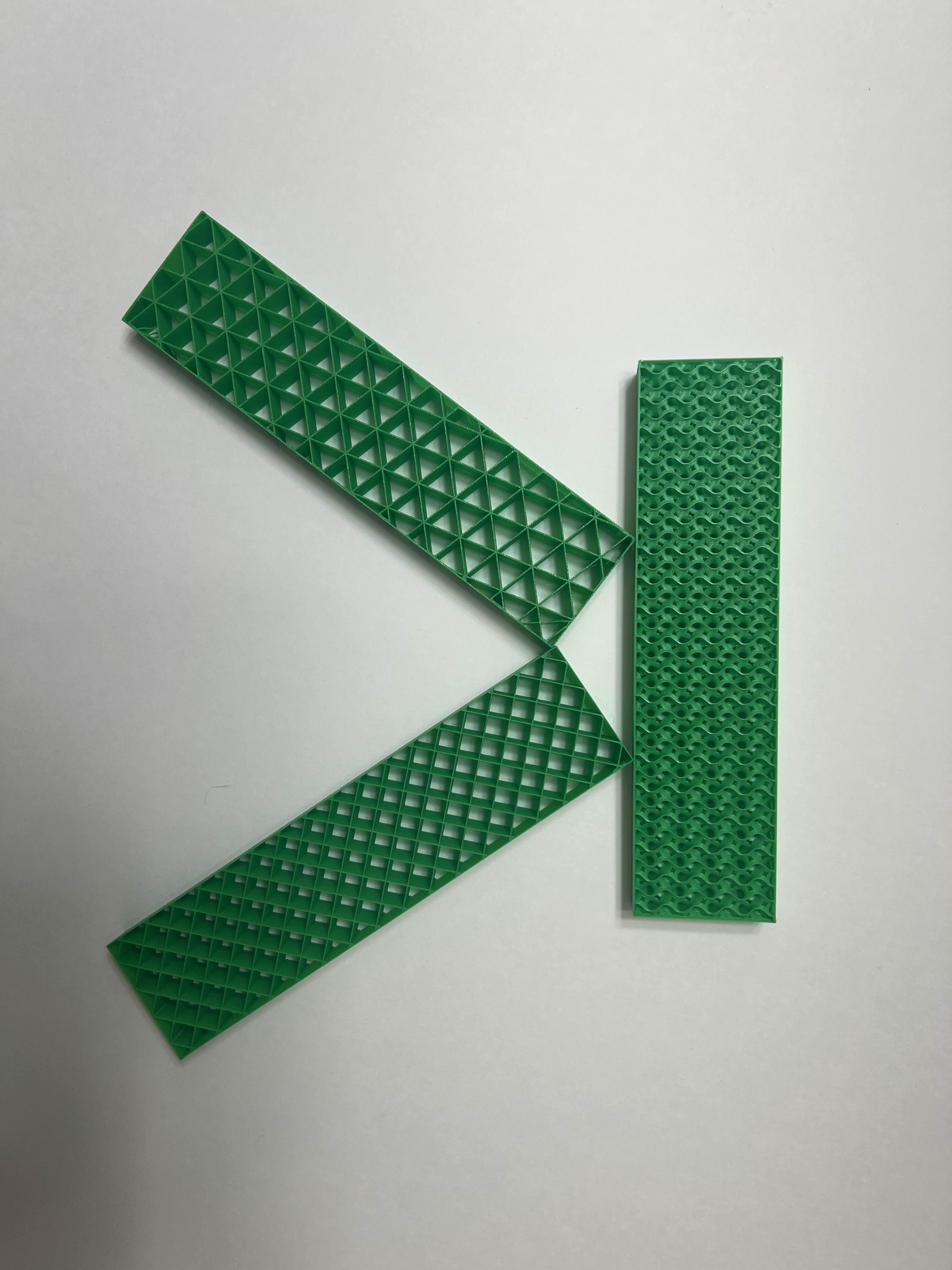
Our work results in a set of grasshopper scripts that, given a simple surface or polysurface in Rhino (one that does not have different branches at each layer), will generate a linear toolpath that includes one of our two created infill patterns, given a density that is controlled by the user. Test models (described briefly in Process) were created using a straight extrusion of a rectangular surface as the rhino model with dimensions (200mm W x 50mm H x 16mm D) with 10% infill density. Similar models were printed using the Grid, Gyroid, and Triangular infill patterns generated by the Bambu Studio Slicer as a control group for our strength tests.

Strength Test Results
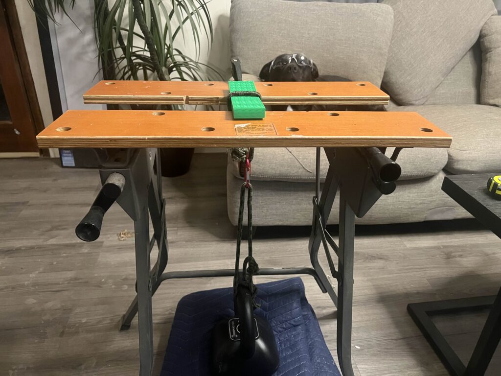
The tensile strength of each test piece was measured by hanging weight plates from the middle of the part and recording the weight at which the piece fails. The amount of end support was calculated by using 25% of the total length for each end. Weight was increased by 2.5 lbs. increments. The test objects were all of similar size of 200mm x 50mm x 16mm. While the Gyroid pattern (unsurprisingly) proved to be the strongest, our program generated trapezoid and rhombus infill did have the second highest horizontal tensile strength.

Generating an infill toolpath for artifacts with z-axis changes
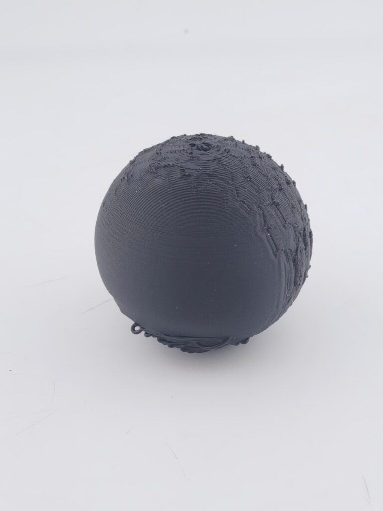
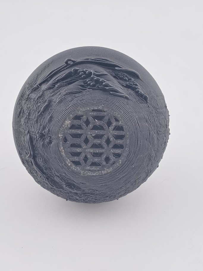
A separate outcome that branched from the initial project was ensuring infill could be properly generated at each layer for models that had rounded tops and bottoms (overall, models where the area is different at each layer). A sphere model was used to test this with 80% infill. In the CURA visualization below of the toolpath generated by ExtruderTurtle, it can be seen that our scripts run into little difficulty generating the infill in rounded models. Observable in the final print, the infill had little issue during printing, while the exterior shell of the model faced difficulties. We will attribute these imperfections to a lack of support generation and the fact that only one wall is used for the outer shell.
Program Generated: Sphere with 80% infill (Time: <11 hrs)
Future Work
- Allow slicing for complex models: Our current work is only designed for objects with a set of single, connected layers. The toolpath generation script can be improved to include objects with multiple non-connected segments at different layers. Additionally, a bottom and top layer generation can be added, which was not included in the current work in order to observe the infill in the final prints.
- Optimizing toolpath generation for infill patterns: We did not implement any changes to how the infill toolpath is generated. One proposal focuses on generating a toolpath that follows a Eularian Path (a path that visits every edge once) or a Eularian Circuit (a Eularian Path that starts and ends at the same vertex), then performing a depth-first search if a Eularian Path does not exist. One paper introduces another approach using a Euler transformation to construct a 2D lattice from a unit cell that garuntees a Euler path exists (Gupta et al., 2020). This approach would be especially great for generating infill patterns that can be used by continuous extrusion printers.
- Create infill patterns that introduce non-linear curves.
Reflection
Creating a new infill pattern from scratch is far more challenging than anticipated. Since we are meticulously controlling the printer’s movements at every step, even a minor miscalculation can compromise the entire print. We observe this in our test prints, where connected nodes between trapezoids tend to serve as breakpoints in the model as it is where the infill lines start and end during printing. The resulting grasshopper program can easily be used to test further infill designs and opens a simple way for users to try create their own infill patterns if further refined.