Slides
Introduction
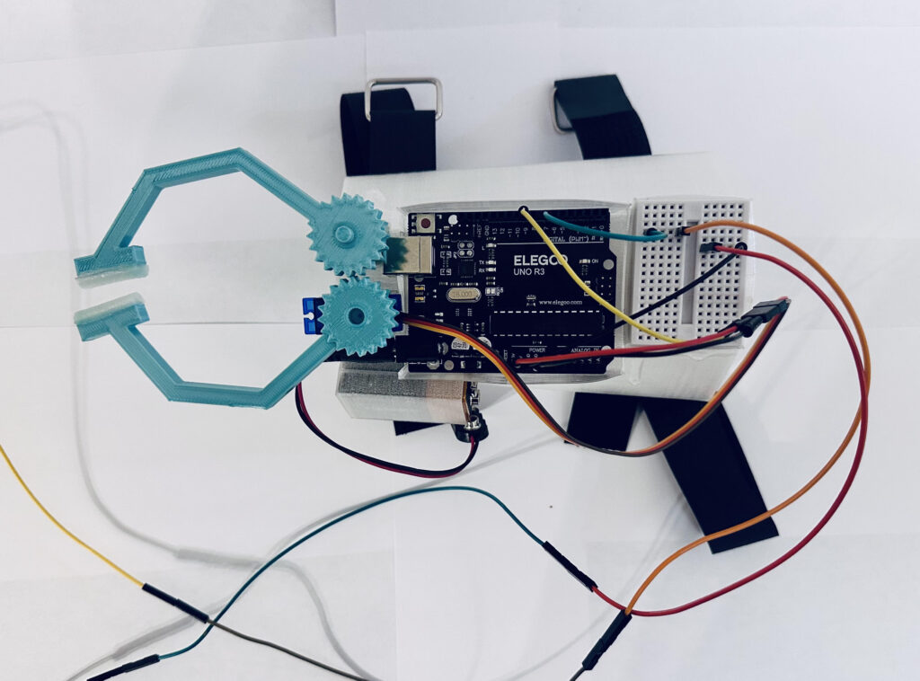
The goal of my project was to be able to use the computational assignments we used in class to generate 3D pieces to create the necessary shapes to assemble and create a working robotic hand. Pairing my newfound 3D printer capabilities with my past robotics experience helped aid me by merging the two together to create a customized robotic hand with a TPU arm base to attach the hand to and to the user themselves. My aim was to create a more refined and improved robotic hand that would be a revised and revamped version of my high school design. Essentially, the robotic hand would act as a substitute for anyone missing or unable to use their hand properly. This would be a more affordable and DIY version of a robotic hand that could easily be printed out and assembled with a simple Arduino kit. This design would allow for a portable and compact version of the larger pick-and-place designs that are out there which are not designed for a mobile capabilities, are large and clunky, and aren’t tailored for a human to wear. The base that houses all the components is roughly 5 inches in length and due to its TPU material composition it is able to flex and contour to the users arm and with the added velcro straps even smaller sized arms can use it. The end effectors are about 4 inches in length with TPU grippers and in total the whole robotic hand design is only 9 inches which is very small and compact since the end effectors are designed to reach past the wrist and act as the new hand. The extended button allows the user to use their arm as usual and by attaching it to the inner arm and near the armpit they can easily press the button against their side and open and close the end effectors.
Background Research
When it comes to relating this piece to previous work in the field the options are endless. This design could essentially be a low-level form of prosthetic for an individual who has lost their hand and can provide them with the ability to grab things and place them as they please. This design could be enhanced and added to a full scale robot that has claw like hands to grab and place different objects that it is told to do. The design is so small and compact it could replace any non-technological substitutes like a hook and allow users to make new end effectors and provide them with a variety of hand options when necessary or go with the tried and true claw design. My initial thoughts when making this design was that I had to incorporate the servo with a gear mechanism that would open and close the fingers of the robotic arm. With the two research papers I found, I was able to draw inspiration from their gear designs. I took my own approach by utilizing the triangle gear code we created in assignment 2 and created my own gear that had an internal cutout for another gear to attach to. They had very symmetrical gears that would perfectly open and close their designs, but due to the angled fingers that I had with my design I had to shift how the gears aligned and alter the end piece of the finger so they would be touching and all for the fingers to actually grip an object. My design included a 9V battery as a power source since I wanted to keep the design compact, I had previously used a AA battery pack to power my older design in high school and that just took up too much space on our final design. I took a different approach to their gripper servo technique and had one finger on the robotic hand that was placed on a servo replica that would just allow it to spin freely when the other finger which was directly attached to the micro servo and they would move in synch when the button was pushed to open and close them. Since both of the designs from the papers were for stationary robotic arms I did not need to include the elbow or the shoulder servos simplifying my design and approach. I did have to make a base for the entire contrapment, but since this was for human use I had to make the base more comfortable than a rectangular block on your arm and I contoured it to taper at the front where the arm gets small and wider as it gets closer to the elbow. I also made sure to make it a proper shape that allowed for a flat and large surface area to attach everything to.
Link to Background Process for V1: Andrew Holmes – Final Project Update – COMPUTATIONAL FABRICATION
Process
The overall process for this design started out with the gears I knew I had to use a gear design to elevate the final product and create a better design than I did in the past. I focused more so on the gears and how they would be placed since they had to work in tandem together to properly open and close. When I first created the gears they had no interior cut out as I was just trying to make sure they would print properly and with defined teeth so that they could rotate with one another. Once I had a decent gear I realized that I could create another interior gear that could connect to the servos and I could place them on top of the servos neatly and not have to screw or attach them in any other way. Once I got the right size hole for the servo to go into the gear I was able to attach it and rotate it with the servo. Off the bat I knew I wanted to do a curved claw design for my final project since the designs I had seen were the flat fingered ones and that design didn’t seem as fun as the one I wanted to create. So I design the individual pieces for the fingers using the python code from the parametric vessels assignment and I created 3 for each side rotated at about a 45 degree angle to create that signature claw look. After working with that I needed to make the piece that the grippers would attach to so I downsized the finger pieces and unioned them with the rest of the piece. I then quickly created a triangular gripper for the claw to get a good idea of how they would open and close together. Now that I had the claws I needed to work with the servo components and wire my arduino board to the breadboard and the servo so I could actually see one of the fingers move back and forth. I was able to find the simple code from the Arduino website that they use for public domain and have it located in the examples section in the Arduino IDE. I followed their instructions from the website and made the button mechanism to rotate the servo “open” and “close.” Once I had this design set I just had to upload the code from the arduino website and it worked the servo would rotate 90 degrees to open and close the finger. Once I got this going my next task was to make something to place the second finger for the robotic hand on. So I thought since I only had one servo why not just make a PLA version of the servo and just give the finger a place to rest on that would be the same height as the real once and this would allow for the two fingers to connect and rotate with one another. I had some minor troubles getting the size since I was eyeballing and didn’t have my caliper at the time, but I got something really close to it and settled with what I had. The final thing was the arm base and I wanted it to wrap around the arm but not be entirely a circular design because I wouldn’t be able to properly place all the components on it. I opted for an 11 sided shaped which was fine but definitiely didn’t have enough surface area still to put everything on. Halfway through the print the TPU clogged so I lost almost 8 hours of print since I fell asleep while it was printing and it was just printing into thin air with nothing coming out. I reprinted the design and gave it a 5% infill since it was going to take a long time. Once I got the base all done I started to attach all the pieces and quickly realized 5% wasn’t enough and the arm base was so flimsy that the weight of the robotic fingers would squish it down or make them fall left and right. Plus the fingers would barely make any contact with the grippers since it was a small surface area to grab something.
After seeing these issues I knew I had to increase the infill for the design but that would take more time, however, looking at the first version of my college design I realized how much wasted space I had so I knew I could decrease the arm base and make things more compact. I also realized that if I made the design a hexagon I would have a nice flat surface to put all the components on. I got a bit more curious and started experimenting with different sized shapes for the arm base and quickly realized the wrist section of my arm is thinner than the middle so I should make my arm base reflect that realization. After printing it I quickly realized just how much more useful it was going to be and how much sturdier it was for my components. Since I didn’t like hot gluing all my components straight to the arm base I decided to make sleeves for all of them and attaching those with hot glue so I can take my pieces in and out as I please. This part of the process was slightly annoying since TPU takes longer than PLA and if the sleeve was just slightly too big or small it wouldn’t work for my design. I tried intersecting copies of the sleeves so one side would be open to pull the components out, but this didn’t work, similar to how my arm base was made by intersecting two hexagons together. So I just made certain sleeves like the battery have an open design where I would remove the top layer in Cura since despite the designs having an open face it still wanted to fill them. Once I got everything glued on and in their sleeves the design was almost complete. I just had to extend the button out by connecting the wires together and wrapping the final ones around the Arduino button that was in my kit. I poked myself an cut my self with the wires and the button I don’t know how many times, but after some time I was able to get the button to work away from the breadboard. After that I cut some slits into the base to put my velcro and then I printed out one more thin piece of TPU to house the button and cover so that it could be attached to the side of the user using a velcro strap around their arm and by pressing the button against their side. I tested the arm out with lighter materials since it didn’t have a good grip. I really couldn’t even grip the broken pieces I had from my old renditions of each part, but I found out its really good a picking up cotton based products like cotton balls which is a nice start for some, but with a stronger servo I could do more.
Outcome
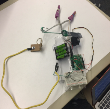
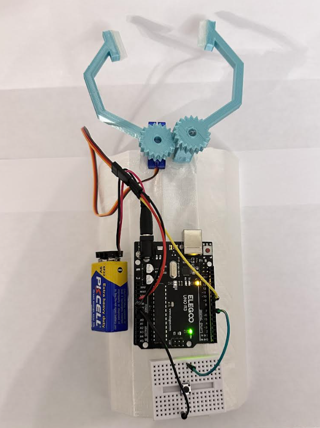
I think the outcome for my design was a great success I definitely created something that was more refined and simplified compared to my previous design in high school. Just looking at the first version I had for the final project update shows just how much progress I’ve made since then. The first design was just so large and ugly to look at, whereas the one I have now is much more simplistic and seems like a much more feasible option if someone just wanted to create a robotic hand and use it.
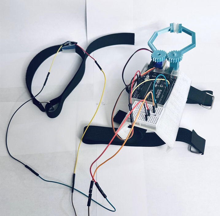
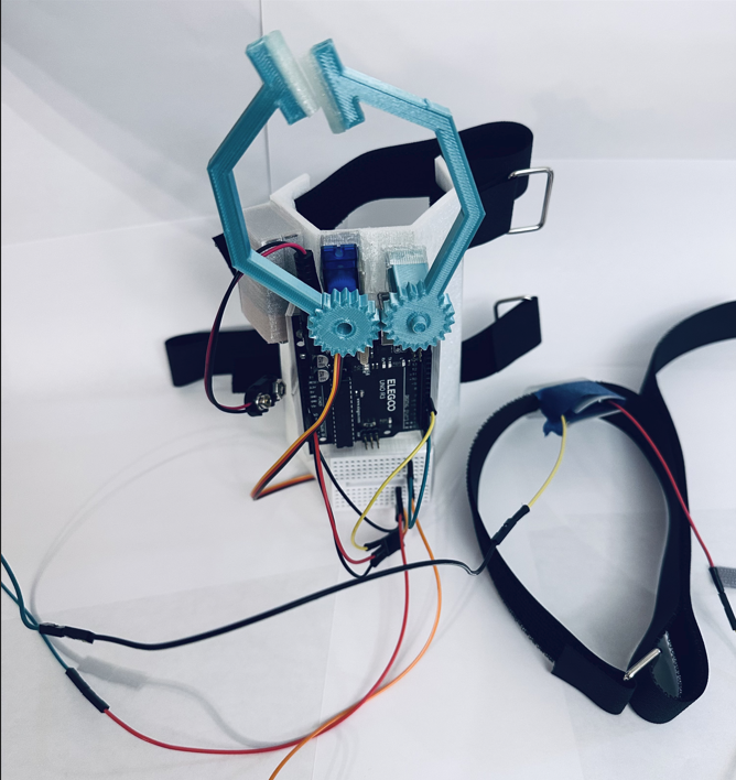
Now looking at my newest design that I am submitting I am very happy with it considering I redid the entire base to be smaller, have a different shape, include a tapered width, and ultimately including the Velcro straps to tighten the design to your arm. There were still some issues with the height of the servo and the servo copy that I made so the gears didn’t entirely match up and wouldn’t spin together. I fixed that issue by using a caliper to get precise measurements for all my designs. Also since I lessened the sides from the original base it allowed for a more flat surface to put the servos and the other components on. Since I increased the infill for this new design it also was more sturdy and allowed the side by side fingers and their gears to be more level instead of leaning to the left or right side of the arm base since they were slightly top heavy. I like that I had a more useful method of attaching the button to the body of the user since I used TPU to cover the button and extended the button out to make it more accessible instead of being on the robotic hand itself. The extended and different colored wires is the only issue I have with it other than the servo being too weak to hold anything besides a cotton ball. The overall design though I am very pleased with and might continue to work on it over the winter break!
Future Work
I believe if I had more time to work on this project, the main change I would have made would have been to purchase a stronger servo motor. When I purchased my Arduino kit, it came with a simple micro servo, and this component does not have the strongest torque and gripping power that I was looking for. However, the micro servo served very well considering it was very compact and fit exactly what I needed when I wanted to make this design as small as I could. The higher torque servos are much too large, but I feel like if I rearranged the components and used more of the surface area that I had on the arm base I could shrink the overall length of the design on the users arm and extend some stronger and longer end effectors for the design. Another modification I would have liked to make would be to solder all the wires together. This would allow for permanent connections and I wouldn’t have to deal with multiple wire connections and accidentally disconnecting one from the breadboard or the push button. I wanted to make this design fairly reusable which is why I made the sleeves for all the components. However, if this was something I was looking to place in a competition or anything I would be more willing to bite the bullet on the components and have them permanently connected to the arm base, but for now I can easily take apart and put the design back together again. Lastly, for the button, I would like to find a more user friendly button that is made of rubber or has an attachment to the Arduino push button to make it more functional. The button overall is just too small and could be easily missed or even squished by the user if they push too hard breaking the leg connections to the breadboard.
Reflection
One of my biggest takeaways from this assignment is that even building the smallest things will take a lot of work and the margin of error for measurements is so little and the outcomes are much more exaggerated on a smaller scale. If you are off by a mm or two that’s the difference between your components fitting snugly within one another or simply being too large to fit or too small and being loose. I can’t tell you how many times I printed different sized holes pieces and shapes changing them by fractions of a mm to get them to fit. The main kicker was every print, no matter if you gave it the same dimension each time, your printer likes to be just slightly off in size every other print and there isn’t consistency in your design. This means if you break something you might have to print it 2 or 3 times before you get one that fits right again. This was my main issue with my gears attaching to the servo and the servo copy that I made. The same goes for the component sleeves that I made for the battery, arduino, servo bases, and the bread board. I also had my first major issues with clogging when it came to working with the TPU material. It was definitely much more exciting to work with than PLA since it was clear and you could see the internal designs made from the fill. However, I wouldn’t recommend making large prints that take more than a few hours with it since I had multiple clogs either from the filament being twisted and melting funny inside the nozzle. My first arm base print I did at night so I could wake up to get it done. However, I was awoken early in the morning by my mother asking me if the nozzle was supposed to be just moving around in the air. I realized that the nozzle got clogged and thought that was fixed, but there seemed to be like three burnt clogs within the tube still and I had to use the filament change setting on my printer to keep trying to push them out and heat the nozzle enough to remelt them. Other than it clogging, I think TPU is very versatile since it can have a low infill and be soft, a high infill and be solid, or a nice flexible material that has some structure when you print it out around 50% or so. I also learned just how precise you have to be with your angles and shifts since that was a lot of the work when it came to creating the pieces and joining them together with a union block. If things don’t align perfectly it’s a lot of back and forth with the slider until you can finally see them aligning. And even when they align on the the software that doesn’t mean you are going to get that exact result when you feed it into the 3D printer, it can only be so precise with its movements and there’s some things you are going to have to work around in order for your creation to become physical because the software design made it seem like it was going to be super easy to make, but putting it together physically definitely wasn’t what I expected it to be despite my past experiences.