Progress:
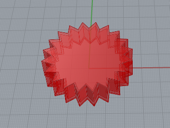
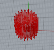
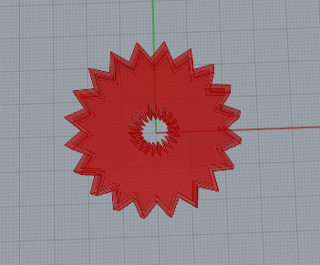
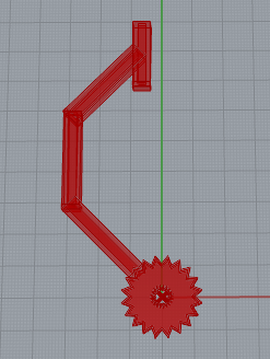
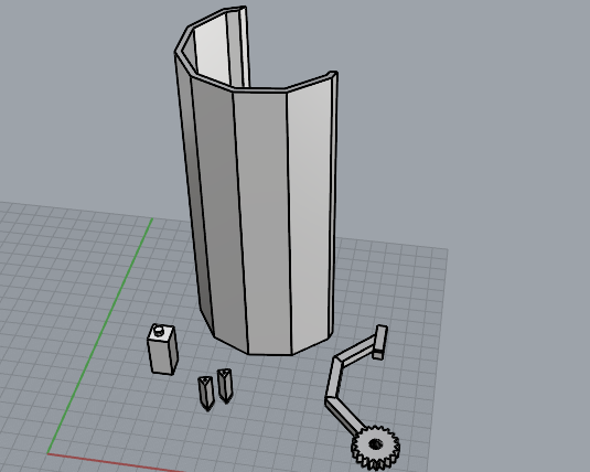
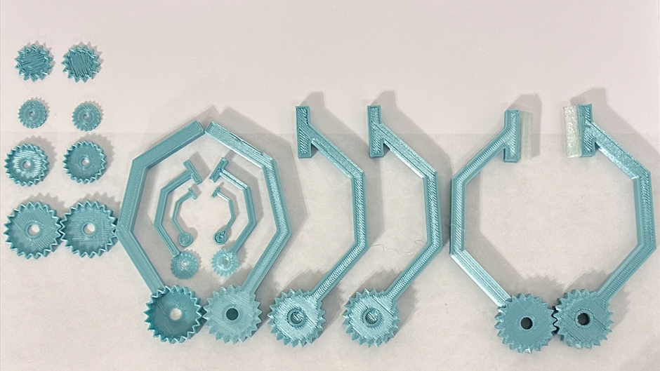
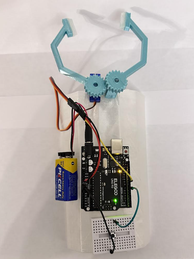
In the beginning I wanted to use some sort of gear system to open and close the end effectors for the robotic arm. The servo had a gear, so I knew I needed to attach them to that somehow. I started off by using the vessels project and altering the code to make my own version of a gear. Once I made that I needed to have a cutout for the servo to go inside the gear that I created. So, I made an internal gear to subtract from in order to place the servo gear inside. I had the design open-face so only one side of the gear was closed. Instead of making a second reflected arm I just made the cutout for the servo all the way through and capped both sides so that it could be printed out and just flipped over physically. I did the cut-out all the way through because I realized that by just having a small subtraction for one print meant that I couldn’t flip it over and I only had two left handed end effectors.
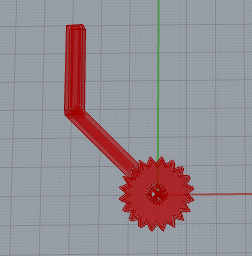
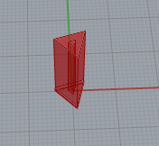
Adding the joints and arm portions of the end effectors was fairly simple. I made rectangular pieces and connected each one together at roughly 45 degrees to the right of the one previously. I added another piece at the end that was roughly half the size of the other rectangular pieces and this piece is what the TPU gripper piece would connect to. I printed out triangular grippers for my robotic arm and these were made fairly quickly with the 3D printer. Once I finished the End effectors for the robotic arm, I moved on to how I would make the base for them to be placed on. I realized that I could just attach the end effectors to the micro servo that I was attaching one of the pieces to. This elevated the effector high enough and acted as its own base.
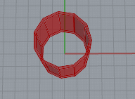
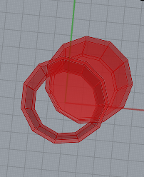
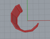
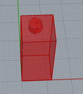
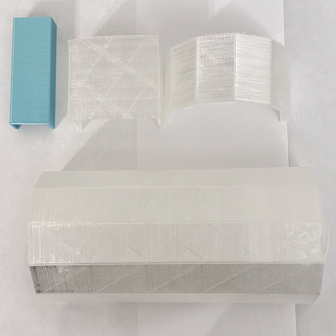
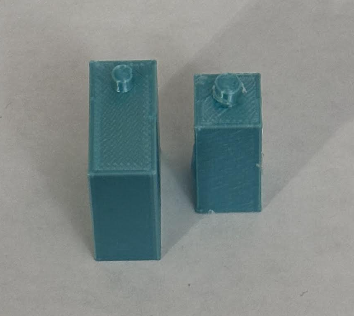
Then I realized that I need the other effector to be elevated and have something to rotate around. So I made a 3D printed model of the micro servo using some rough measurements from a contractor ruler that I randomly found in our house instead of our smaller traditional ones. Once I did this I moved onto the arm base, and so I created a rectangular box and thought about slipping my hand in, but I wanted to reduce the printing and material use so I intersected a copy of itself to make half of the base. I printed out smaller versions out of PLA so I wouldn’t waste time and I quickly realized a rectangular plastic base was not going to fit or be comfortable on a human arm. So I decided that I was going to use TPU for the arm base so it was more flexible and would contour to the human arm much more easily. Also instead of using a 4 sided base cut in half I upped the sides to 11 and it made it more circular enough to fit the human arm and wrap around without being too round and not a viable platform to place all my electric components.
I was able to download the software for my Arduino Uno board and implement a simple code to rotate a servo 90 degrees each time a button was pressed, I wired all the pieces together and powered the board using a 9 volt battery with a power adapter.
Next Steps: I was sick for a whole week, so the print and physical form of my design wasn’t as finalized as I had hope for by this time. However, some things I’ve noticed so far is that I want to make the height (z) in my end effectors to be thinner so that it fits more properly on the servo and isn’t so heavy that it wants to pop off. I bought a caliper to make all my designs more precise, especially the size of the gear holes so that they aren’t too loose and fit snugly onto the servo gear and the servo copy model I made. I also want to make some subtractions from the TPU arm base so that I can easily place the servo copy on top of it. I’m thinking about making little pegs it can connect to and having cutouts for those pegs in the servo copy.
After putting on the TPU arm base I noticed that it wasn’t flat enough so I might reduce the number of sides so that there is a nice flat top for the components to sit on. Also, the base is a little too flimsy, so I want to increase the infill from 5% to 10-15%. I will also want to shorten it in length so it doesn’t take as long to print since I can use the side parts of the base to attach all the components.
When it comes to the servo, I’m thinking about making a sort of internal sleeve for it to go into the arm base that it fits perfectly in similar to how an iPhone box fits neatly inside itself. The same goes for the battery pack, Arduino uno, and the mini-bread board so that all components are inserted into the arm base and won’t need any sort of glue to stick and can be taken in and out to be reused.
The final thought I had was the button placement since it can’t be located on the arm which would defeat the purpose of having to use your other hand to open and close the robotic arm. I was thinking about placing the button under the user’s armpit, so they have to move their arm to open and close the robotic arm without any additional help. Technically speaking this should be a robotic hand since if someone needed a full arm, they wouldn’t be able to access the button if they had nothing to squeeze it with. But for now, we are assuming that the person has an arm and just needs to use the robotic hand to grab and place things. Also, for the arm base to stay attached to the user’s arm I need to subtract some rectangular pieces from the side of the design so I can add Velcro inside that can be used to tighten or loosen and attach the robotic hand to the user.
Documentation:
Prototype:
Deliverables:
- Base Used to Attach to Human Arm
- End Effector (Fingers/Grippers)
- Arduino with Wiring and Button Connection
- Base to hold End Effector Attached to Arm Base
Timeline/Milestones:
November 1 – November 12: Design & Prototyping Phase
- Base Design: Model the base attachment in Rhino/Grasshopper, designed for secure mounting to the arm.
- Gripper Design: Design the end effector with TPU padding for better grip.
- Servo Layout: Plan servo placements for optimal movement, working with the Arduino to configure basic control functionality.
November 13 – November 26: Assembly & Testing Phase
- 3D Printing: Print the base and gripper parts, ensuring durability and accurate fit.
- Servo & Arduino Assembly: Connect the servo to the effectors and integrate it with the Arduino to test initial movements and gripping capabilities.
- Mounting Adjustment: Refine the arm base design for better fit and comfort, making any necessary adjustments.
November 26 – December 8: Finalization & Testing Phase
- Integration Testing: Run movement tests on the arm with different objects, checking for stability and range.
- Optimization: Fine-tune servo responsiveness and grip strength on various test objects, refining Arduino code as needed.
- Final Adjustments: Adjust fit and weight distribution of the base for comfort