Welcome to my last individual post of the semester! First, it’s been an exciting journey the last few months. While I didn’t quite learn what I thought this class would teach, I have learned quite a bit about computational design, and I look forward to applying what I’ve learned from these projects to the final project that Ricardo Ponce and I are working on, so look forward to when that comes out! Nothing further, let’s get into this exploration of tiling. As a short, one-sentence summary of the gibberish below: This assignment was time-consuming.
Part 1: 2D Tiling
Here, tiling by mirroring (at least) one curve of a given base curve was explored. While the following code is a modification of the code from the class example, it differentiates itself as the example demonstrated tiling by translating the base curves.
4,4,4,4 Regular Tiling:
The following Escher-esque tiling results from using two curves (the left and bottom curves, like the class example). Concerning a base tile, the right curve of the tile is created by mirroring the left curve on the y-axis and translating the mirrored curve to its designated position. The top curve is taken from simply translating a copy of the bottom curve. The Escher-esque curves themselves were taken from tracing a base tile that was created in tiled.art
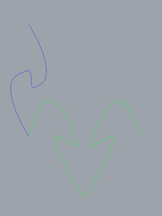
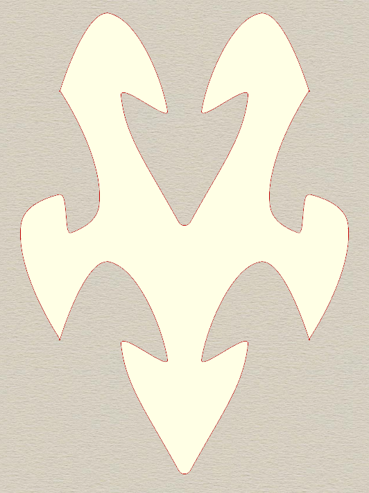
As we all know, the class example does not construct individual tiles before spreading them but rather extracts the tiling from a lattice. To accomplish the lattice (and thus the tiling), two primary changes needed to be added to the python script:
Let there be i rows and j columns:
- At every other column (j mod 2 != 0), the left curve (a_curve) needs to be flipped. Considering that the new curve is a copy of the original curve, this can be done either by mirroring the curve j times at the origin, mirroring the curve twice whenever j mod 2 == 0, or just mirroring the curve every time j mod 2 != 0.
- Since each tile is essentially flipped at each column for the tiling to work, the bottom curve copy needs to be mirrored at every other column before moving.
And that’s it! Afterward, the tiles (and the overall tiling) are created in the same manner as the class example.
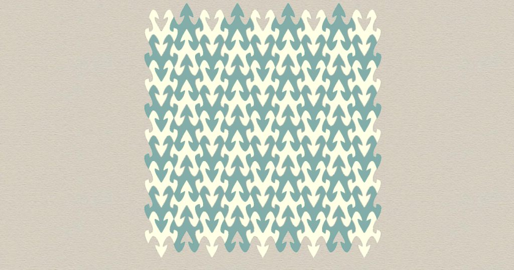
6,6,6,6,6,6 Regular Tiling
The code grasshopper example in class was then modified to create a 6,6,6,6,6,6 Regular Tiling (equilateral triangles) given two base curves, the left and bottom. To create the lattice, these two curves are mirrored (relative to their center) on the x-axis, with the mirror occurring whenever at alternating rows and columns. In the lattice generation script, the base number of iterations is increased to satisfy the base case of a 6,6,6,6,6 tiling when size equals 1.
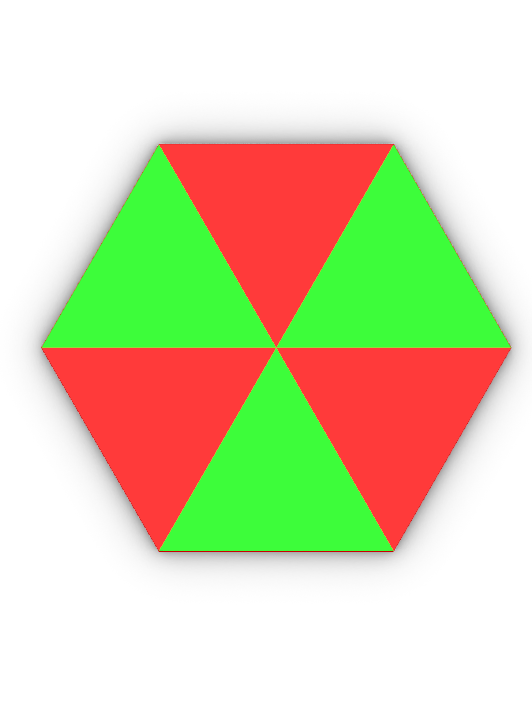
Satisfaction of Base Case
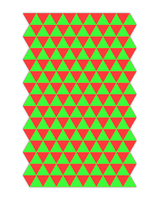
As a consequence of this implementation, we can see that most curves selected for the a_curve input (the left curve) will satisfy our tiling constraints, but b_curves other than a straight line will fail these constraints.
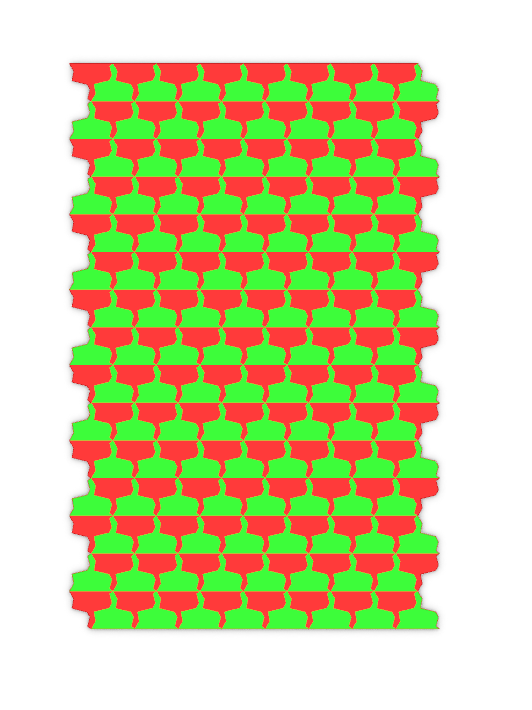
Satisfies Tiling: a_curve
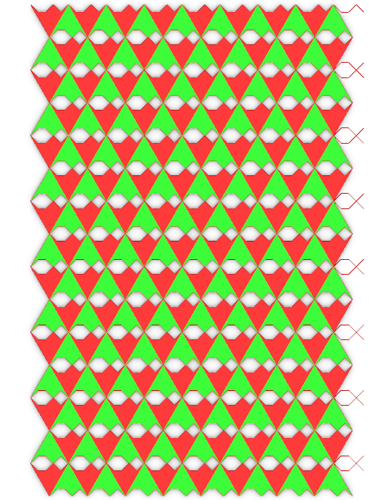
Fails No Gap Requirement: b-curve
Part 2: 3D Tiling
The original goal of the 4,4,4,4 tiling in Part 1 was to create a set of interlocking tiles (i.e. tiles that kind of hold together without glue). As such, for the 3D portion, my original goal was to use a combination of sweep and a boundary extrusion to create tiles that kind of snapped together. Below is a concept design created in Rhino. Among other issues, this design choice did not work as the dimensions prevented tiles from snapping together. I do think this design could still work if the dimensions for the top and bottom curves for the tile are changed, so I may revisit this before presentations on Thursday as I do think it adds more interesting complexity than the submission below.
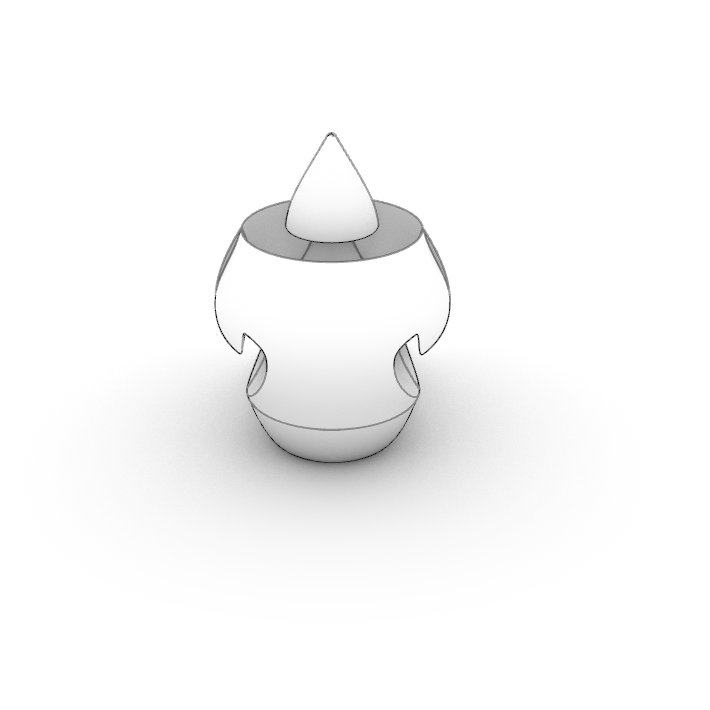
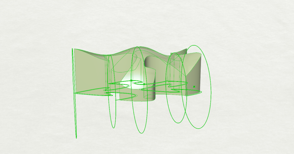
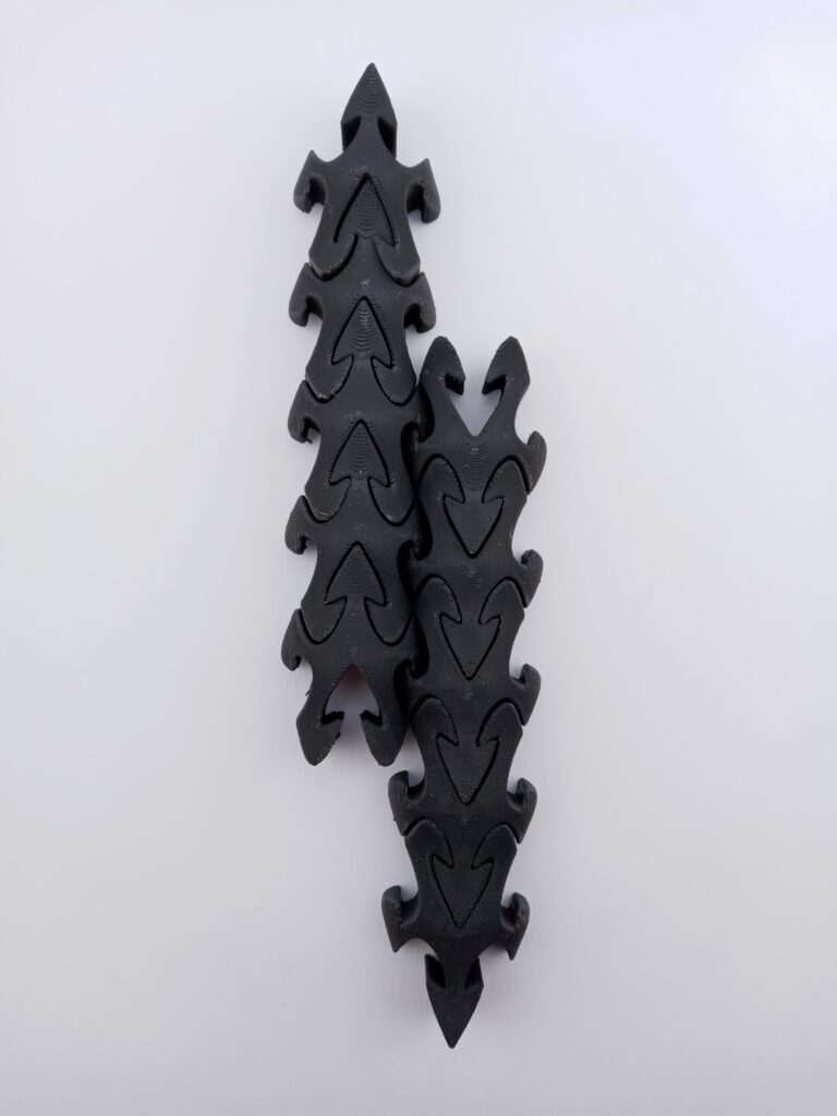
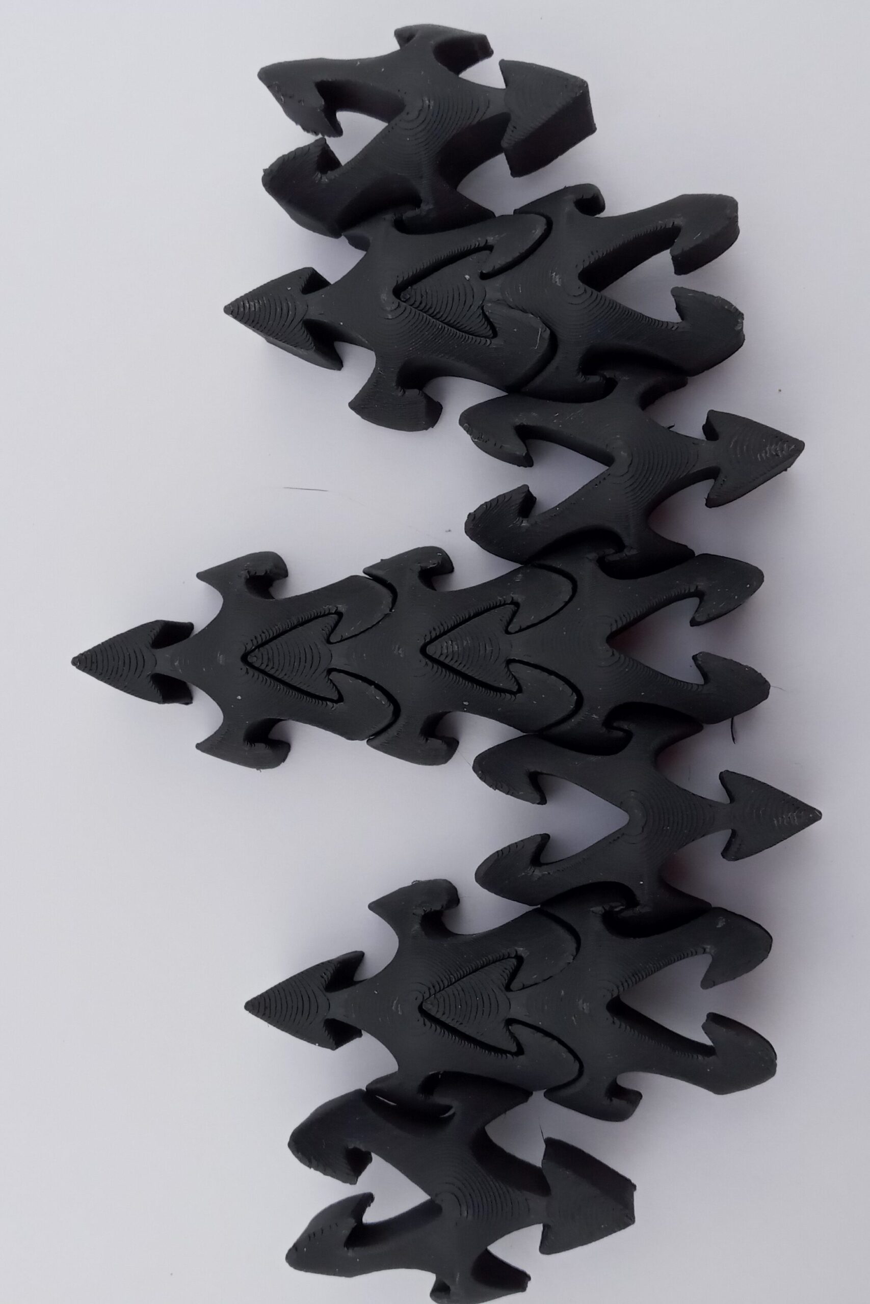
In Grasshopper, I ended up going a different route with inspiration from the way I designed the mid-section. Here is how it works:
- From the left curve, collect points including the two endpoints of the curve and the point with the greatest x-distance from the endpoints
- Create a circle on the XZ-plane for each of these points, where the radius is the distance between the x-axis center of the tile and the point. Additionally, include two circles at each endpoint of the tile with the same radius as the largest circle (this ensures tiles visually flow well on the Y-axis).
- Create a lofted surface with these circles, making sure it completely covers the tile.
- Extrude the tile so it passes through the lofted surface, then collect the result of a BooleanIntersection.
The process produces a similar result to what the ToBoundary tool in ExtrudeSrf is supposed to do in Rhino, except that ToBoundary seems to be pickier about the geometries. One major challenge of implementing this in the tiling code was properly dealing with the results of OffSetCrv, which is necessary for adding some tolerance to the 3D-printed tiles. Essentially, OffsetCrv returns a list of new curves from the result, but does not retain information from the previous curve.
For example, consider I have a tile that is a joined set of four curves (left, bottom, top, right). I would like to access the left curve after offsetting the tile. Now, originally I could call ExplodeCurves and get the first index for this. However, doing the same on the offset curve only returns a segment of the curve I am trying to retrieve. This can turn getting the entire curve a game of guess-and-check, which is very tedious. A workaround (which is not viable in some situations) was to store the offset in a separate variable, then retrieve the needed information (in this case, points for the circles) from the original tile.
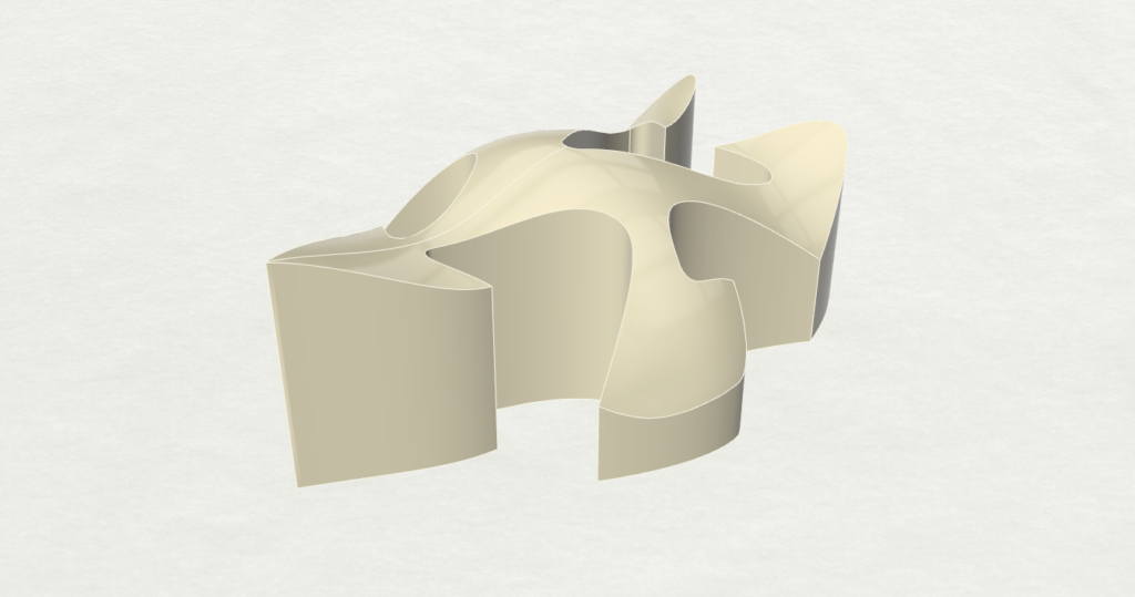
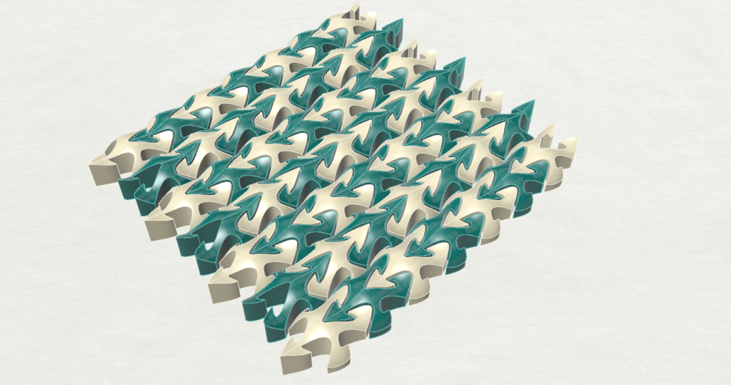
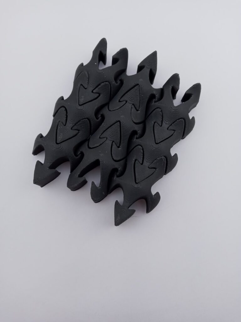
Resulting Tile:
Part 3: Surface Morph
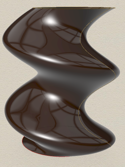
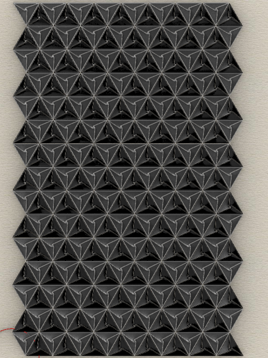
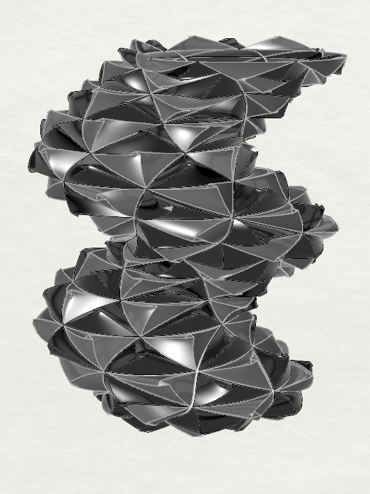
For the surface morph, I created a pattern following constraints noted from the triangle tiling in part 1, then morphed these onto a vessel created from the code in my Parametric Design project. The challenge here was ensuring that the entire surface of the vessel would be covered despite the angle parameter not creating a square (the base tile being a triangle). The trick to solving this: change nothing. The issue with the angle not being 90 degrees comes from how the U and V parameters of surface morph are calculated, so my thought process was that one triangle tile still takes up one of the square tiles, so leaving the base tile as a square should allow the surface to be morphed correctly. This seems to work, though it is worth noting that the A value in the A/B block for the U parameter needed to be increased to 2 as well.
I added a bit of 3D complexity to the tile as well, making little nubs on each tile with a simple loft. This makes a pineapple-esque design.
Hi Nathan,
Amazing work! You wouldn’t believe how much time I spent trying to make inverse lines for the right side of the tiles before I gave up. What you accomplished goes way beyond what I had envisioned, great job!. I am looking forward to your and Ricardos final project.
Hi Nathan,
The way you did your surface morph is enlightening! I experimented with adjusting a couple parameters for my morph, but I was too afraid to try morphing my triangle tiling! I’m glad it worked for you and turned out so cool! How did you get those renders? Is that something you can do in Rhino? I haven’t looked into that.
Hey Nathaniel,
Thanks! The way I did the triangle morph is probably a little inaccurate for the U parameter (the amount of horizontal space that a triangle takes in the bounding box) but for all intents and purposes, I think it came out well. Regarding the renders, do you know the preview with the colors we use for the tiling? It’s just that with one of the display settings in the ‘Display’ tab in Rhino. In 3D renders, lighting is applied automatically by some presets to give a nice glossy effect.
Hi Nathan,
Your titles look amazing. I wish you could see the shape better with the black fillement but oh well. That morph is other worldly; I think its my favorit morph surface so far. In your “guess-and-check” way, I dont understand the solution (workaround) that sometimes works.
Hello Nicholas,
When I say it sometimes works, I mean it’s not a viable option when you need to create surfaces/polysurfaces from the individual curves of the tile after they’re offset. Suppose that you have a tile made from four joined curves (left, right, top, bottom). If you want to access one curve, we need to retrieve the element in the list after calling ExplodeCurves on the tile.
If you call OffsetCrv on the tile, the returned result is a new list of curves, but these elements in the list are all curve segments rather than the four curves that make up the original tile. For example, to get the top curve in the original tile would be like rs.ExplodeCurves(tile)[0], while getting the same curve from the offset result could be rs.ExplodeCurves(tile)[0:3]. As far as I know, it’s a little more difficult to verify which elements here make up the top curve without a visual indication, thus the guess-and-check.
The workaround is to use the curves from the original tile instead and only use the offset result to operate on the whole tile. This works in my design because I only get the individual curves to collect points for creating a lofted surface and then extrude the offset tile. Hope this explains it a little more!