In this project I’ve explored how to work with G-Code, and how to use it to fabricate unique forms & textures that aren’t producible via a typical slicer program.
Process
I developed a Python script that describes several different forms, generates G-Code for printing them, and visualizes the toolpath that g-code prescribes.
My script takes the form of a Python Jupyter notebook, with my own helper class PrintTurtle for generating G-Code that mirrors the movements of a 3D turtle abstraction. In addition to creating G-Code, this class can display the G-Code toolpath as an interactive 3D visualization in Jupyter, using the K3D library.
My design process for this project began with lots of experimentation on how to control and extrude via the printhead of my printer. I had to explore questions like “what’s a reasonable extrusion rate?”; “how close do layers need to be to adhere?”; “what are the useful ways to extrude mid-air?”. I wasn’t able to answer every question, but I did get a feel for workable approaches to printing directly via G-Code.
Next, I wrote a bit of Python to abstract away most of the G-Code I needed to generate to a “turtle” abstraction, and to visualize what forms that G-Code might produce. My code produces a list of gcode instructions from turtle movements, and produces a visualization which highlights movements, extrusions, and “blobs”.
After I had this Python code put together, I was able to rapidly iterate on generating test-forms; mainly to prototype different kinds of texture, as well as movement.
I found a few approaches that I liked which wouldn’t be producable via a slicer, and began iterating on different forms that could incorporate them. For each form, this meant that I would first work towards a visualization that I liked, and then I would repeatedly print and tune it to work with the printer.
Forms
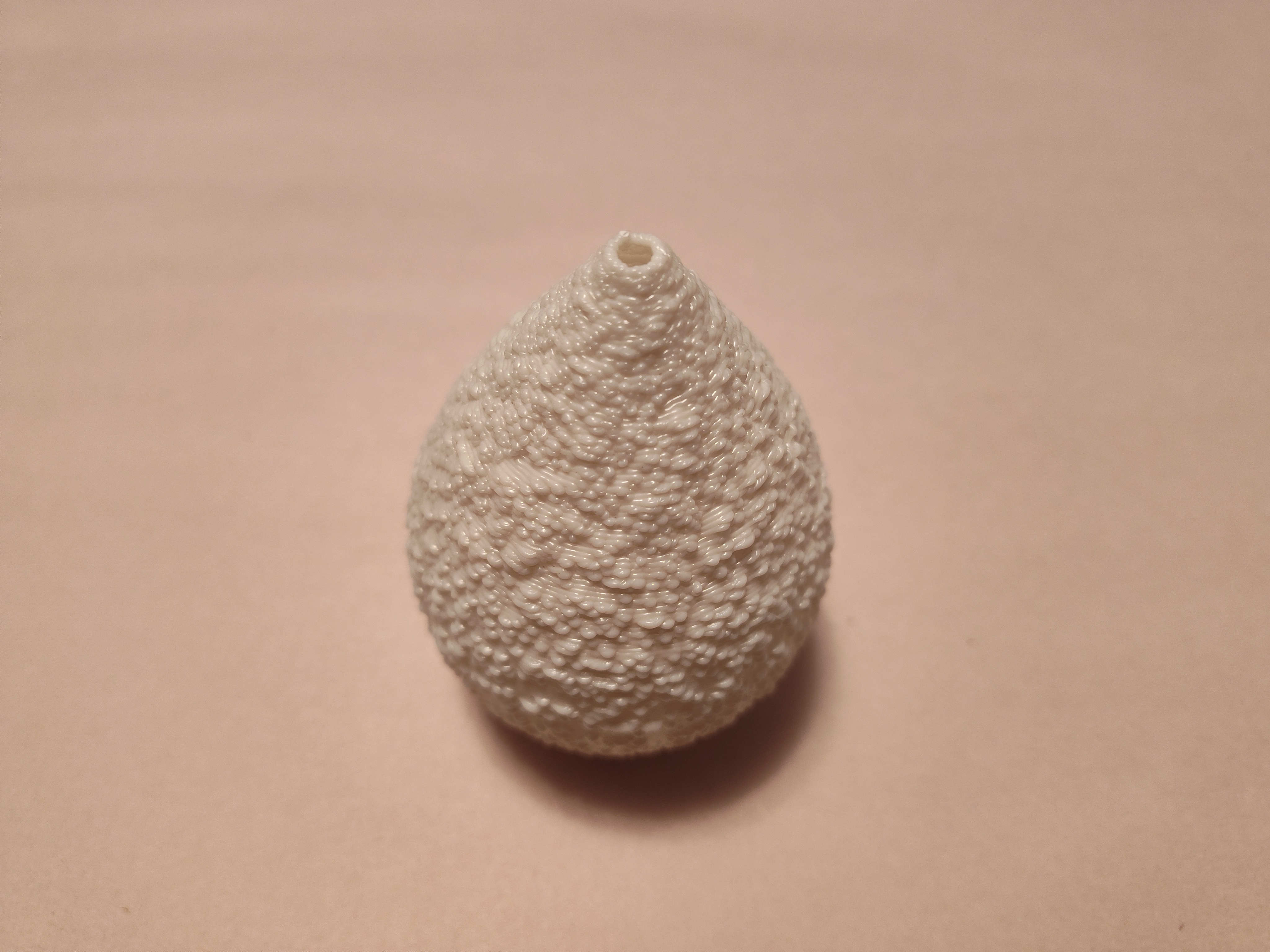
I’ll highlight three different forms here. The first form is a vase-like shell, with “blobs” of random size embedded in its surface. The blobs are created by extruding in-place without any other movement (e.g. “G1 E20 F50”). This produces a very textured surface in which the layers are warped around the inset blobs. A traditional slicer could produce a shell similar to this one, but would not be able to texture it like I have, as I’m effectively varying wall-thickness from point to point.
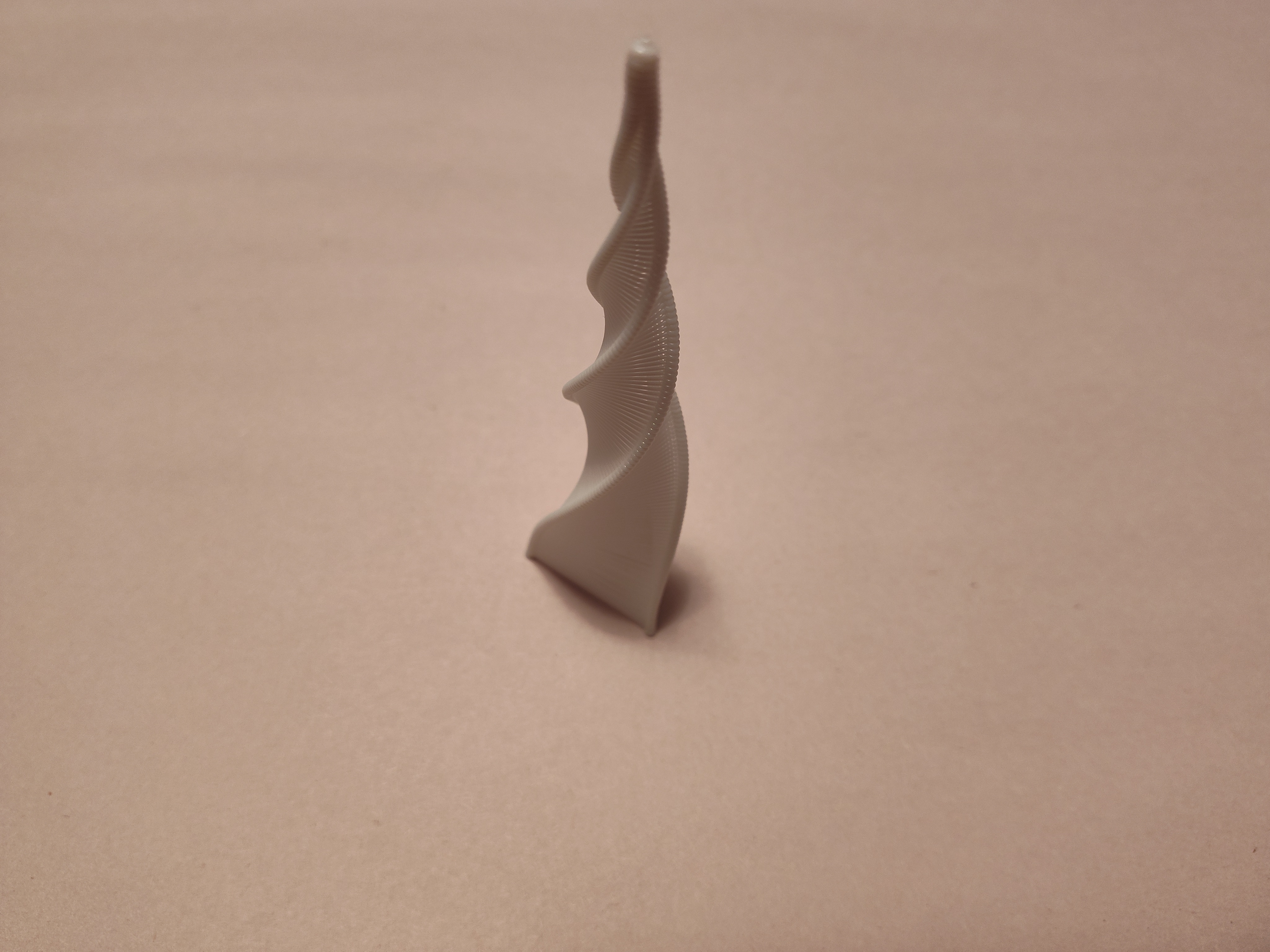
My second form is a tall, narrow, spiraling pyramid. It’s composed of three long twisting columns of blobs, which have uniformly spaced threads strung between them. Neither of the two main elements — the mostly empty walls of strings, and the solid twisting columns — could be produced by a typical slicer as far as I know. Although they’re built in small segments, the columns are orthogonal to the direction a slicer interprets a model, and would be unlikely to be preserved or produced as they are here.
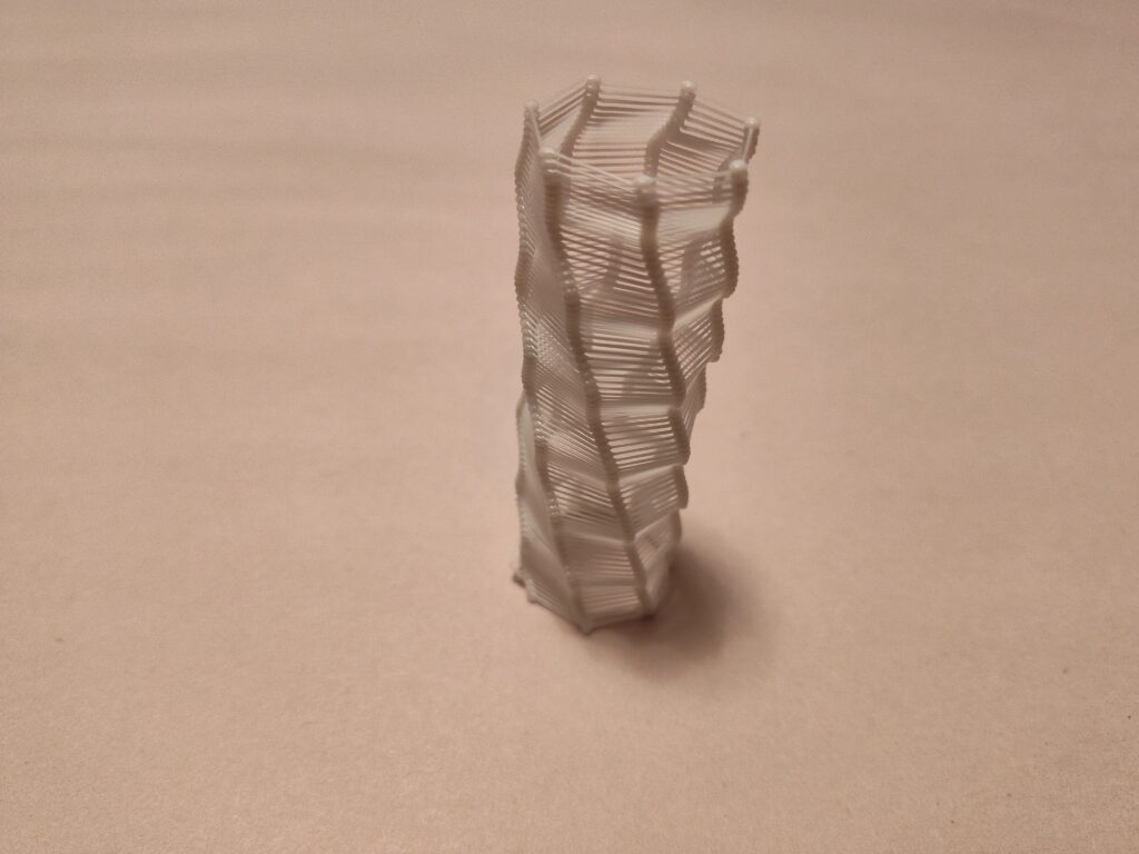
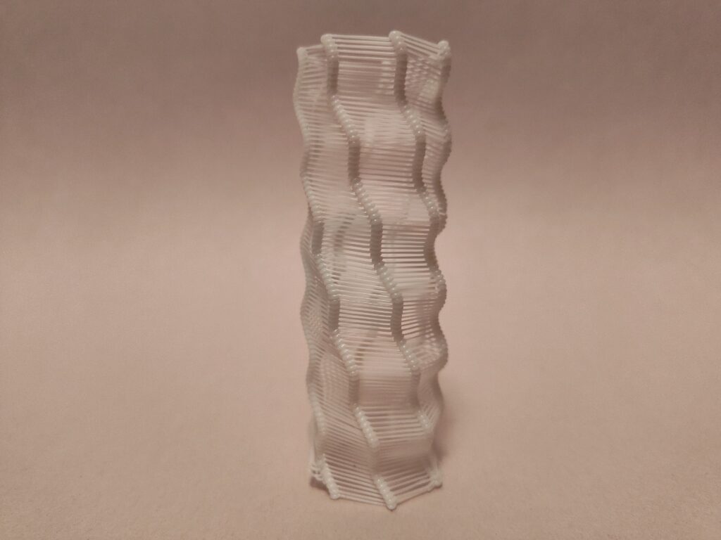
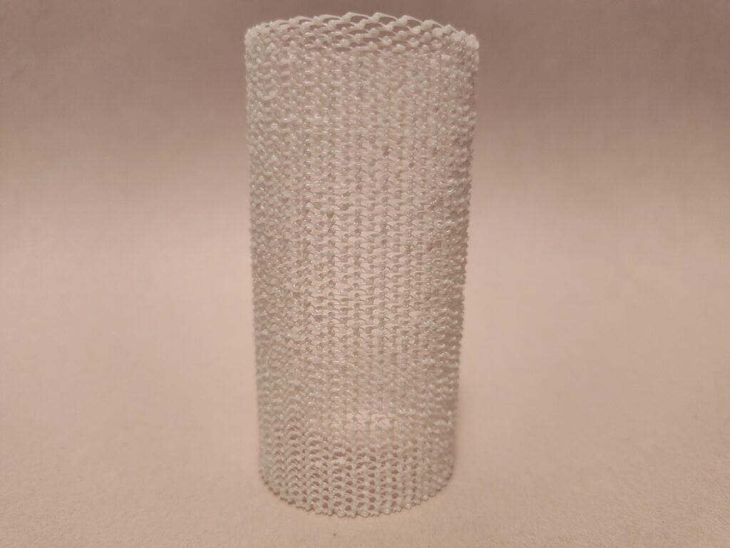
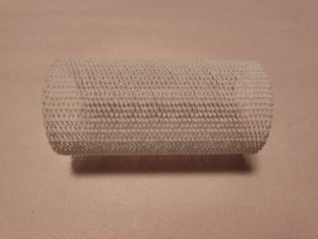
The third form is a sparse cylinder, composed from spheres which zig-zag across Z-layers. This grid of spheres has a transparent, mesh-like look, and is very flexible. I created the spheres using the same “blob” approach as in the previous pieces. A traditional slicer wouldn’t be suited for creating a form like this, where there are no continuous walls of any kind; this form is more like a thin cylinder of infill than a closed printable shape.
Code
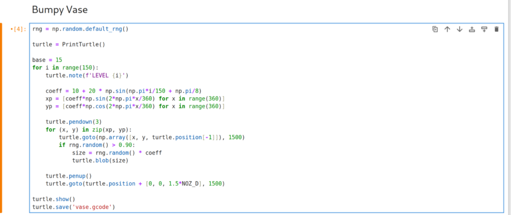
Attached is a zip file containing my gcode files, the python notebook which will produce them, and a HTML version of that same notebook. I’ve also included below a look at the python code I used to generate the bumpy vase, and a snippet of the gcode used to print that vase.
; start_print BED_TEMP=60.0 EXTRUDER_TEMP=215.0
M106 S255 ; turn on part fan
M140 S50 ; Start bed heating
M109 S215 ; Set and wait for nozzle to reach temperature
M190 S50 ; Wait for bed to reach temperature
G90 ; absolute xyz positioning
G28 ; home
G0 X150.00 Y150.00 Z0.3 F1500 ; move to center of print area
G91 ; relative xyz positioning

; LEVEL 0
G1 X0.00 Y17.65 Z0.00 E2.77 F1500
G1 X0.31 Y-0.00 Z0.00 E0.05 F1500
G1 X0.31 Y-0.01 Z0.00 E0.05 F1500
G1 X0.31 Y-0.01 Z0.00 E0.05 F1500
G1 X0.31 Y-0.02 Z0.00 E0.05 F1500
G1 X0.31 Y-0.02 Z0.00 E0.05 F1500
G1 X0.31 Y-0.03 Z0.00 E0.05 F1500
G1 X0.31 Y-0.03 Z0.00 E0.05 F1500
G1 X0.31 Y-0.04 Z0.00 E0.05 F1500
G1 X0.30 Y-0.05 Z0.00 E0.05 F1500
G1 X0.30 Y-0.05 Z0.00 E0.05 F1500
G1 X0.30 Y-0.06 Z0.00 E0.05 F1500
G1 X0.30 Y-0.06 Z0.00 E0.05 F1500
G1 X0.30 Y-0.07 Z0.00 E0.05 F1500
G1 X0.30 Y-0.07 Z0.00 E0.05 F1500
G1 X0.30 Y-0.08 Z0.00 E0.05 F1500
G1 X0.30 Y-0.08 Z0.00 E0.05 F1500
G1 E0.31 F50
G1 X0.30 Y-0.09 Z0.00 E0.05 F1500
G1 X0.29 Y-0.09 Z0.00 E0.05 F1500
Gallery
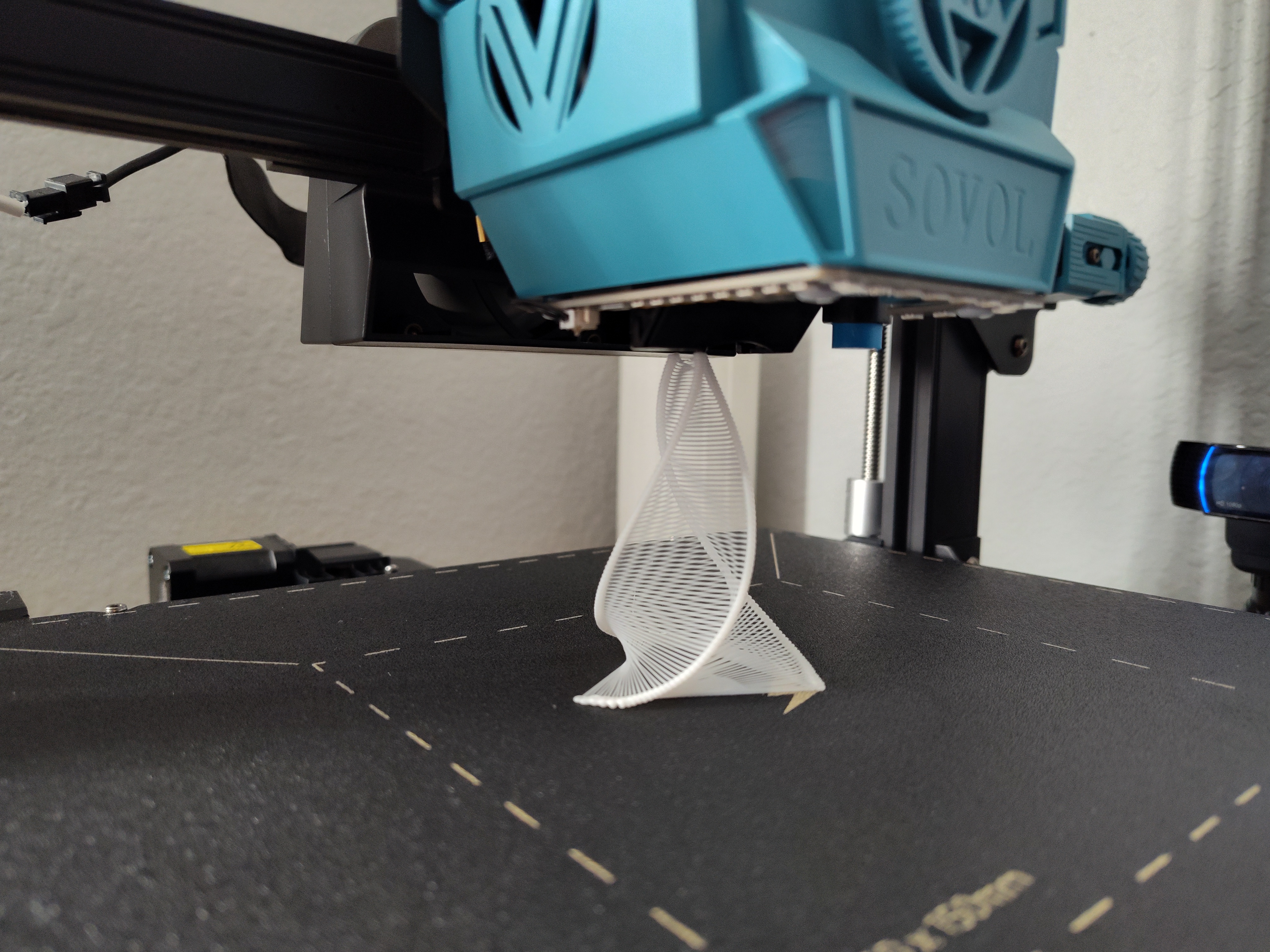
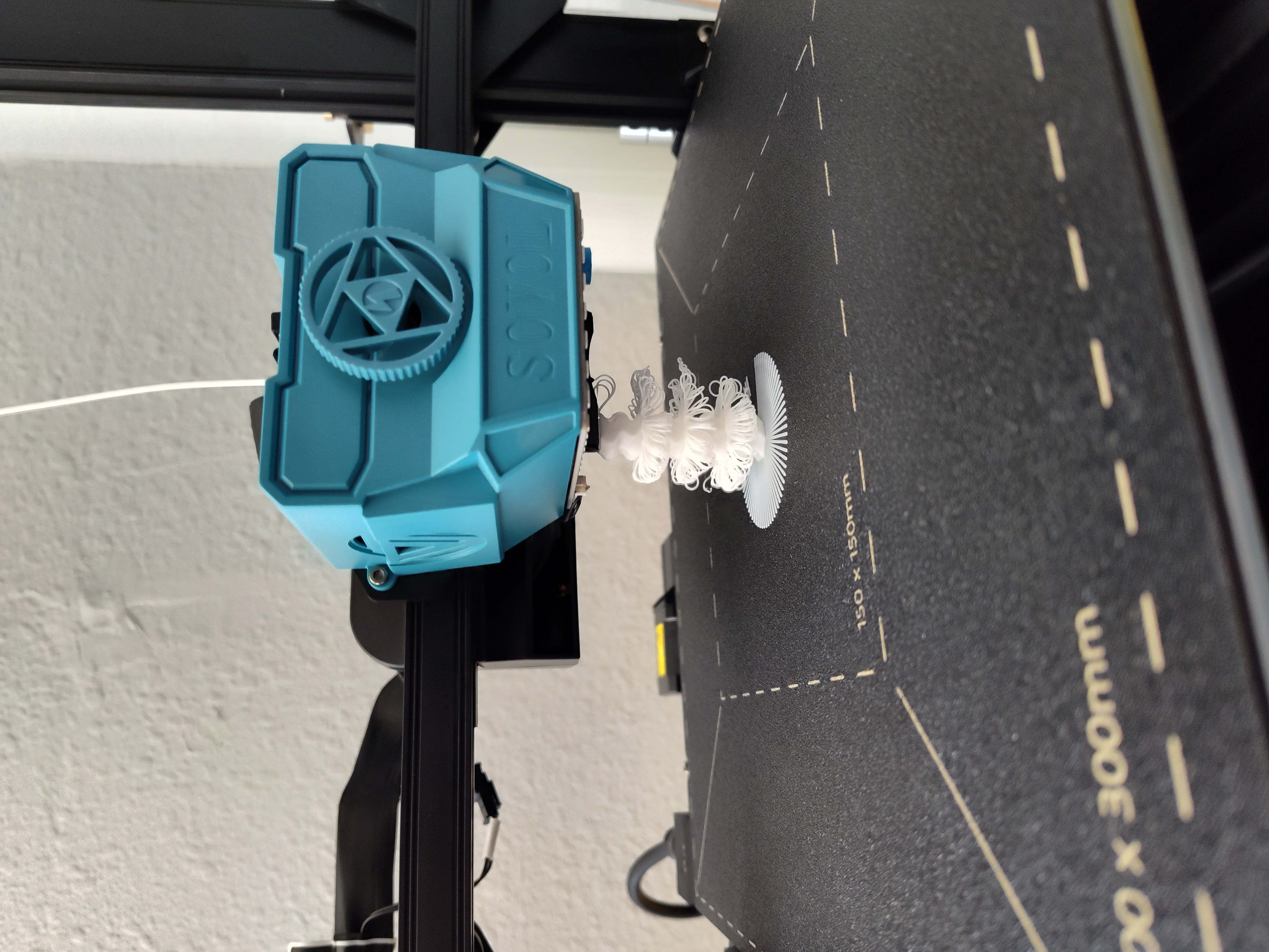
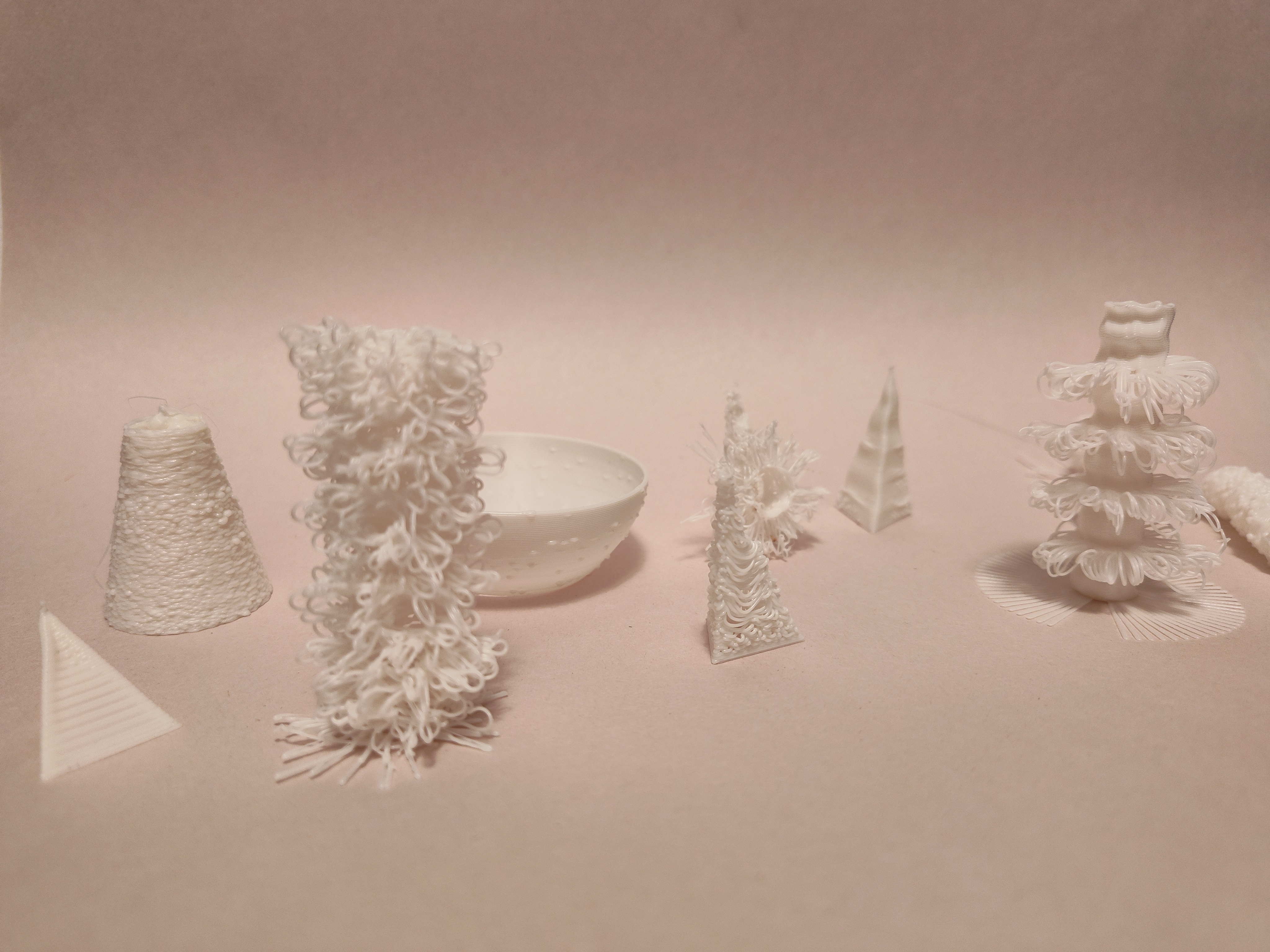
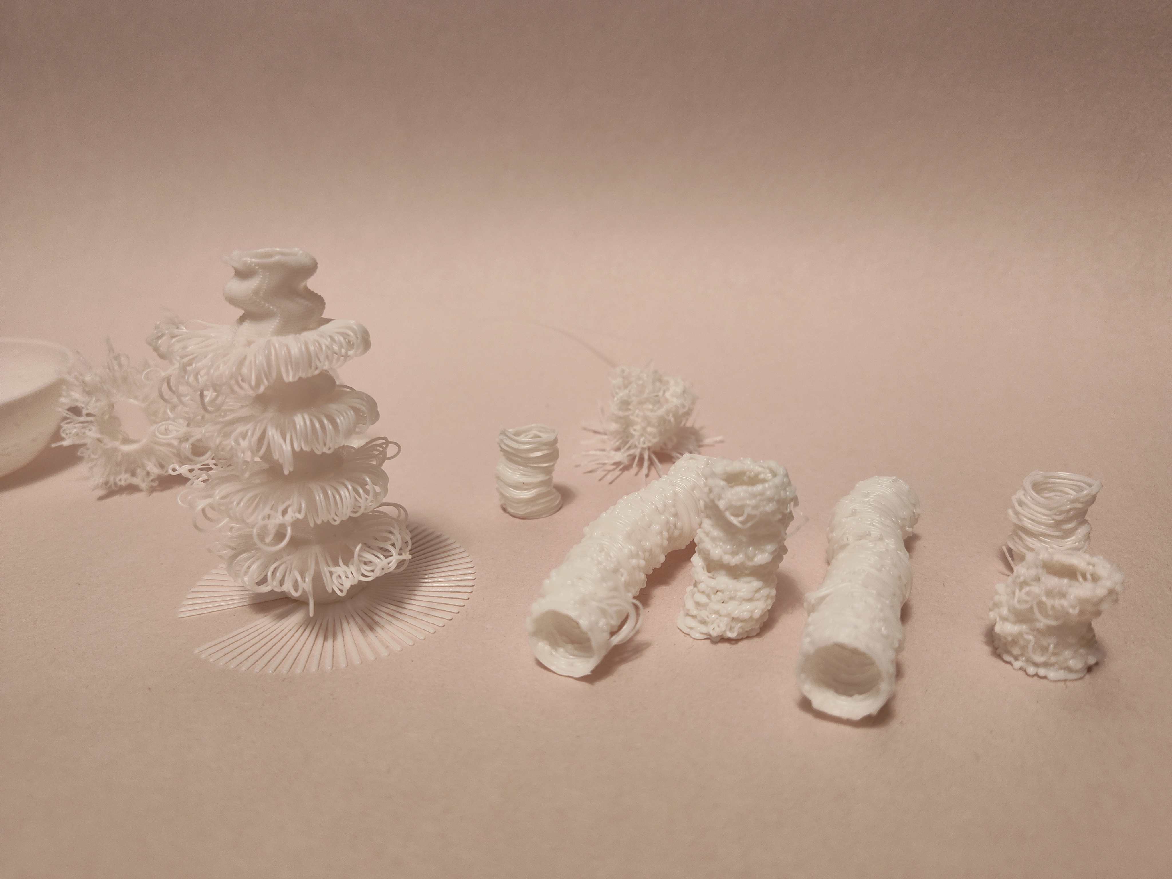
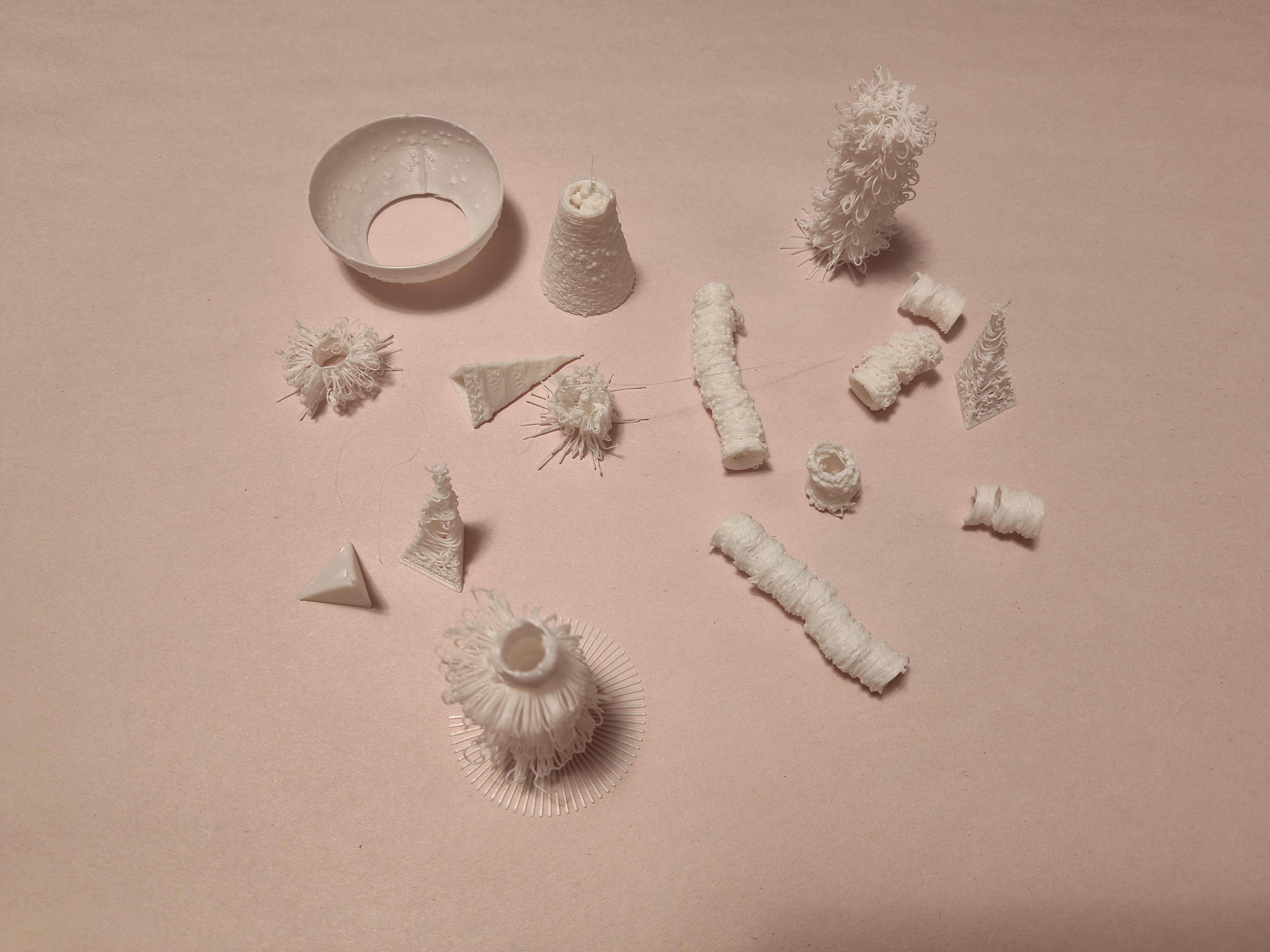
Test & Failed Prints
Visualizations
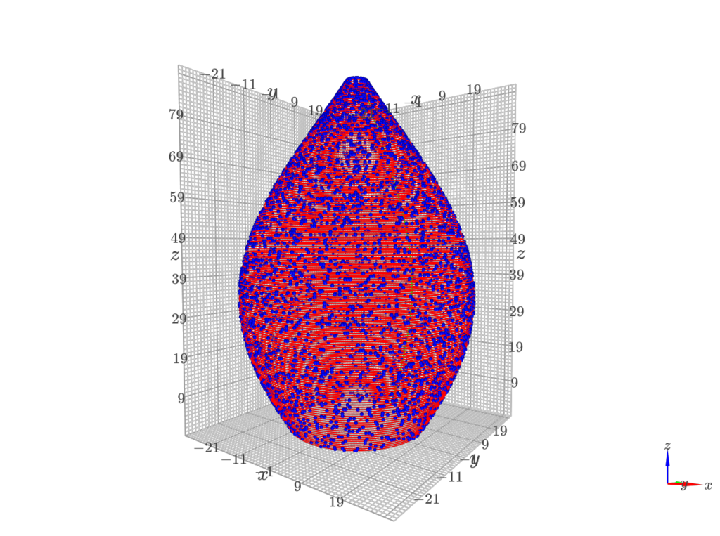
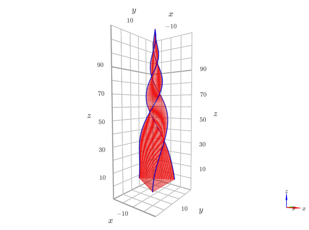
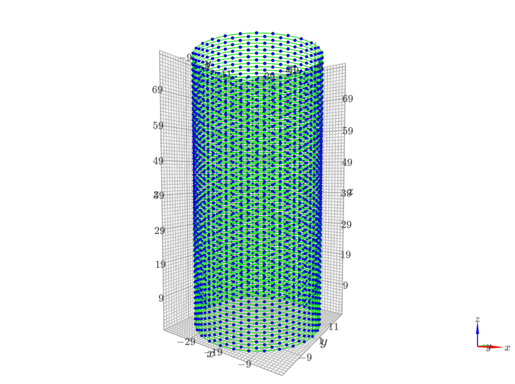
*Cura couldn’t open my G-Code files, so I’ve chosen to include the visualizations from my python code instead.
Final Prints
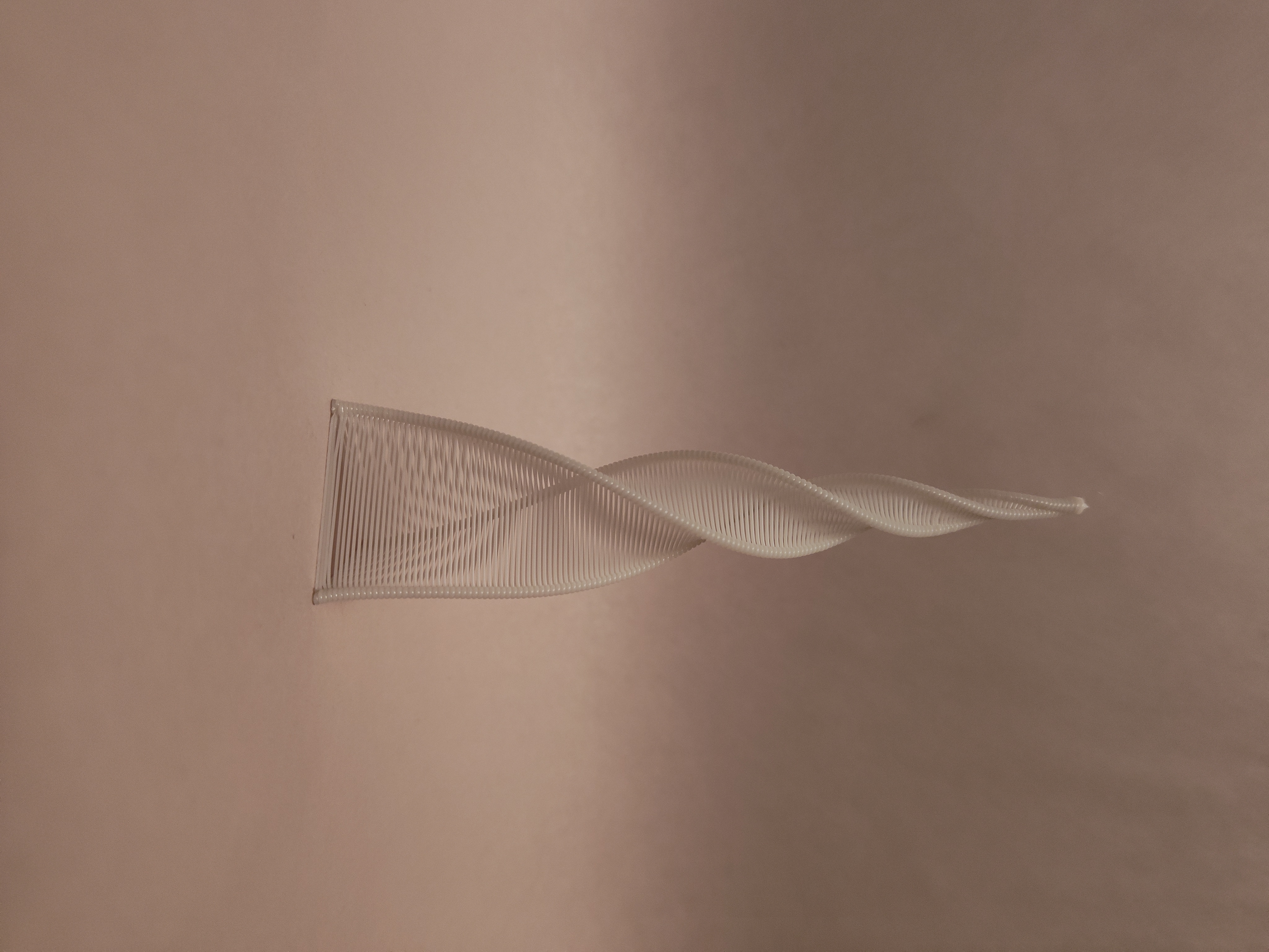
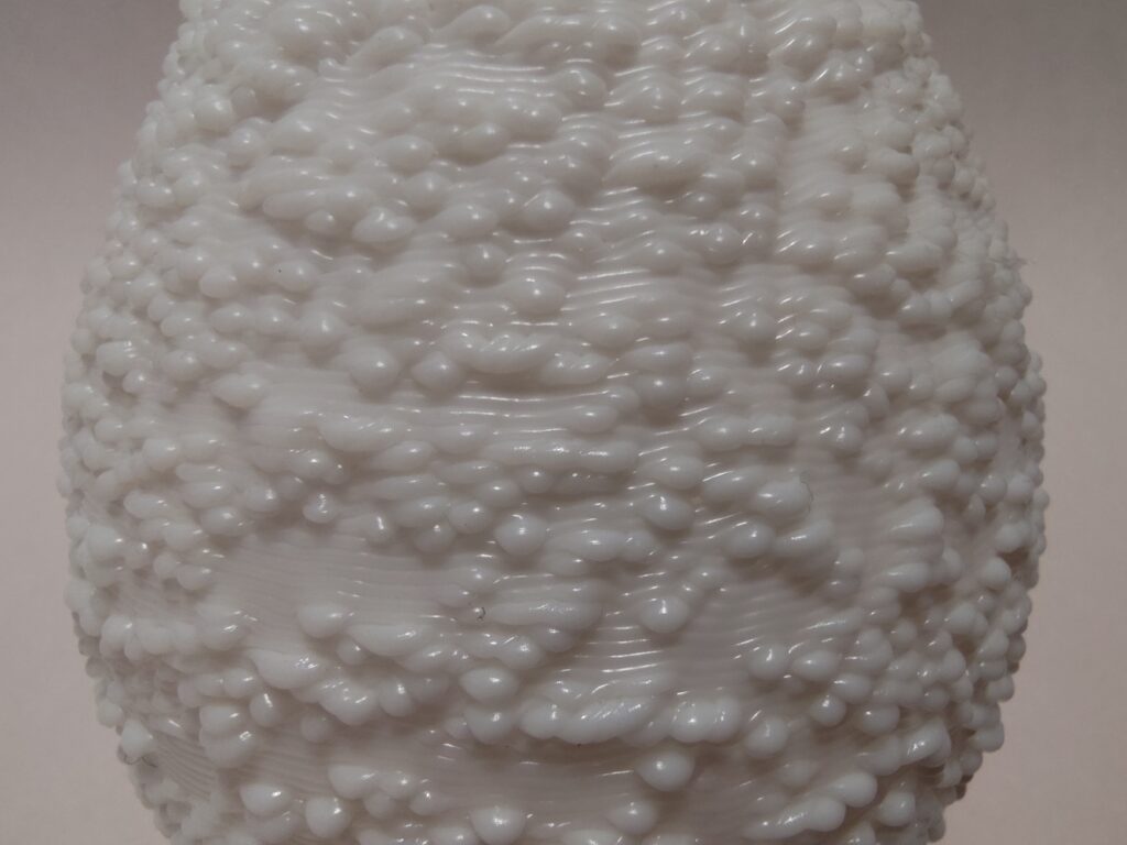
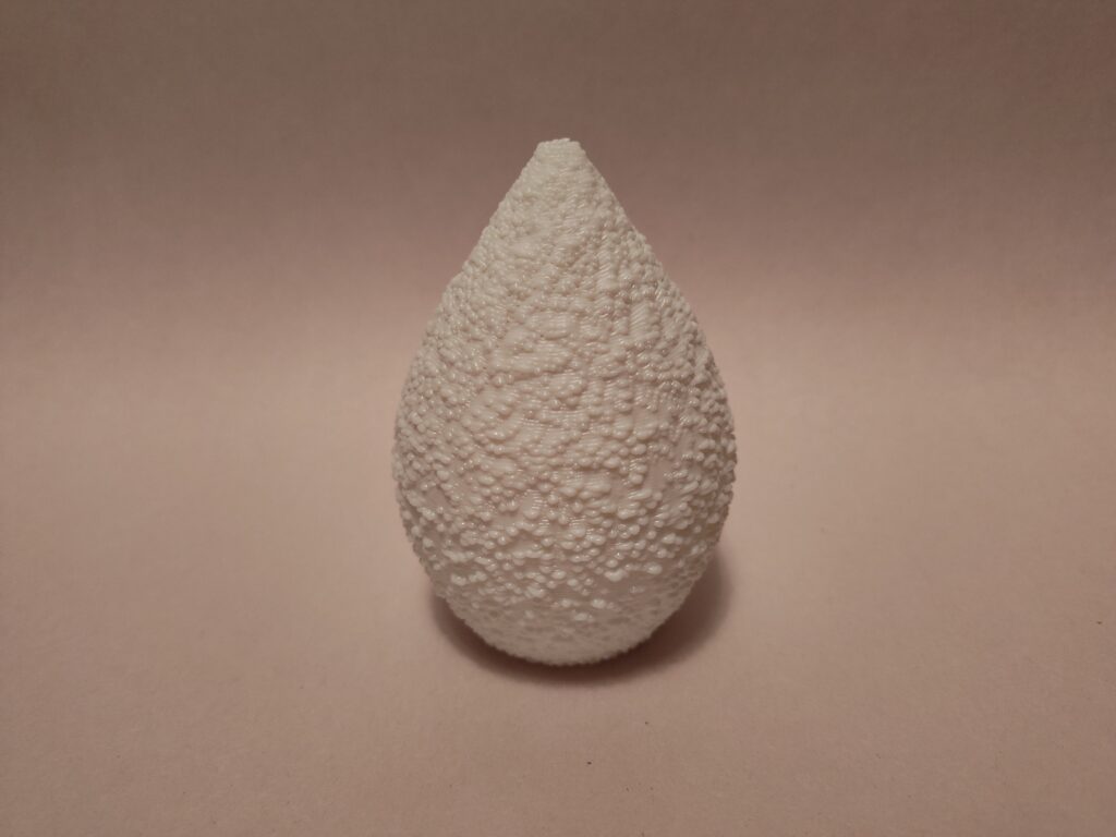
Wow louuis,
I real realy like the last bumpy vase shape. After reading your post it makes me wish I did a stand-alone python. For those half dozen questions did you guess at them or did you test and say close is good? I wished you went into it more with what made the failed prints fail because its only in title of the picture section…
Yo! I’m glad you like the bumpy vase, it was my favorite. As for the test and failed prints, most of them were experiments that didn’t quite capture what I was looking for. Several of these prints involved printing loops in the open air; the main problem with these is that the loops came out much messier than I wanted haha.
Hi Louis, each of your forms are quite different and striking. You mentioned that your process involved iterating on forms you liked, but do you think the iterations led you to a final product that you envisioned originally? Or was it something completely new that caught your eye? It seems like the Python scripts was an effective choice for generating these forms.
Hi Sachi,
I think there was something new that caught my eye, in the process of developing each of these prints. I sort of broadly searched until I found and element that looked interesting, and then honed in on that element specifically.
Hey Louis, your final prints are incredibly cool and interesting to look at! The textures that you were able to create make them striking and the freestanding lines came out well. I also think your process is very interesting as well and the visualizations you included (since you couldn’t load them in Cura) I think they give a better representation of how they would potentially come out than Cura would if they could have been loaded.
Thanks! Yeah, I’m quite pleased with how the visualizations looked. Having those was very helpful for developing these forms. I’m very curious about how/if Cura would render the blobs though.