Grasshopper Code:
Follow along with this post or play with some of the parameters yourself!
https://handandmachine.org/classes/computational_fabrication/wp-content/uploads/2024/09/NathanRoweLA2.gh
Design Process
Creative Process
When starting, I didn’t necessarily have a picture of what I wanted to design more than an idea of the primary tool I tried to use: ExtrudeCrvAlongCrv (or ExtrudeSurface in Rhino Syntax for doing this with a surface instead of a curve). If you remember from Large Assignment 1, ExtrudeCrvAlongCrv allows you to create a surface by extruding one curve on a path that follows another curve while maintaining its initial orientation. A large thing to be considered when using this tool instead of Loft for parametric design (since it is significantly more limited in what you can adjust) is how to create a rail curve that significantly changes with different parameters.
The idea I had for this was to take the radial function for a circle we went over in the class example, and then (approximately) evenly distribute each point along the z-axis up to the required height. This way, different spirals can be created given parameters that change the radius, number of points, and the number of loops (iterations of a circle).
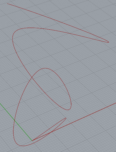
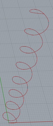
Ensuring that the same height was maintained despite the number of points (and having a near-even distribution of all points) proved to be a little difficult, and many different suggestions existed online. I appropriated the linear interpolation suggestion from this StackOverflow post, where point i replaces t and z = p(t), which worked out pretty well.
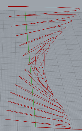
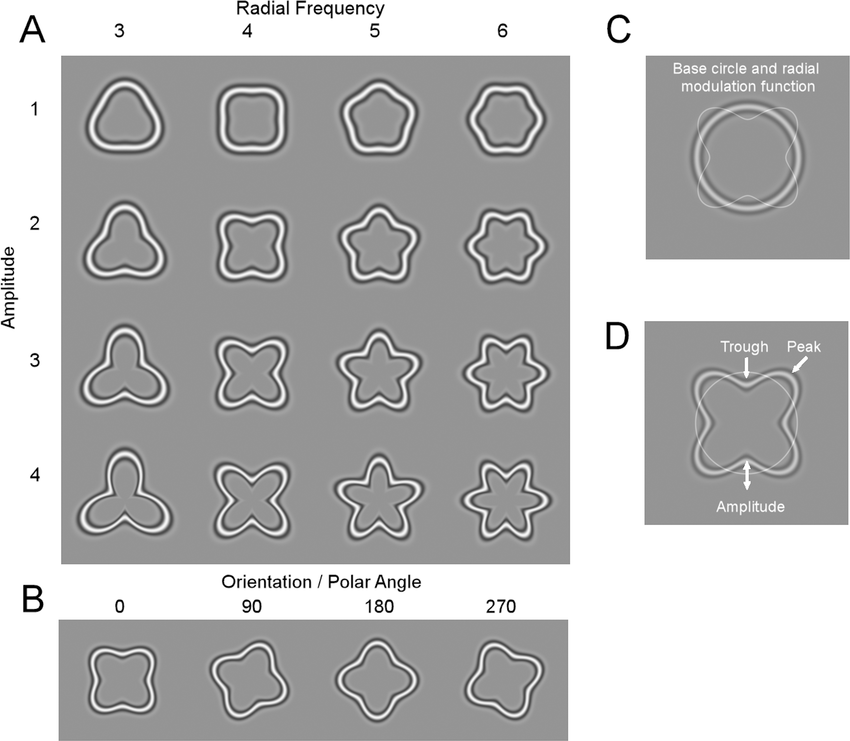
As seen from the examples above, we can probably get some pretty funky shapes using this as the rail curve by changing the set parameters, but what about the base curve? My inspiration for the base curve came from images in a study where a sine wave is essentially applied to a circle, allowing different shapes by changing the frequency and amplitude of the function. This can be done in code by multiplying your sine function by the X and Y coordinates of each point.
Regarding authorship and being the creator of a parametric design, I feel that authorship of the designs has a little less value than making a unique design manually, especially designs like these, where they are just glorified 3D representations of functions and thus simple to replicate. Once the code is written, it is then trivial to produce unique (or existing) shapes by moving a set of sliders. I do think however that being the author of the code itself adds a significant value.
Forms Chosen
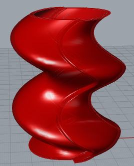
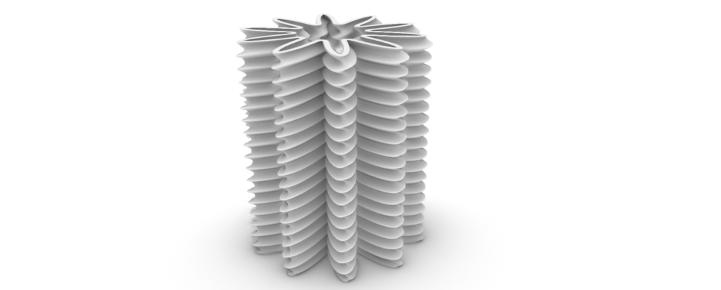
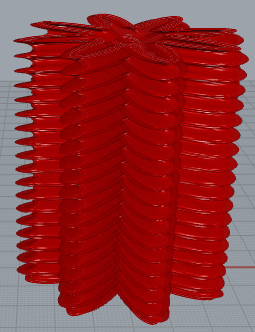
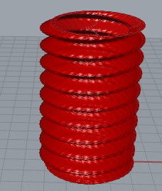
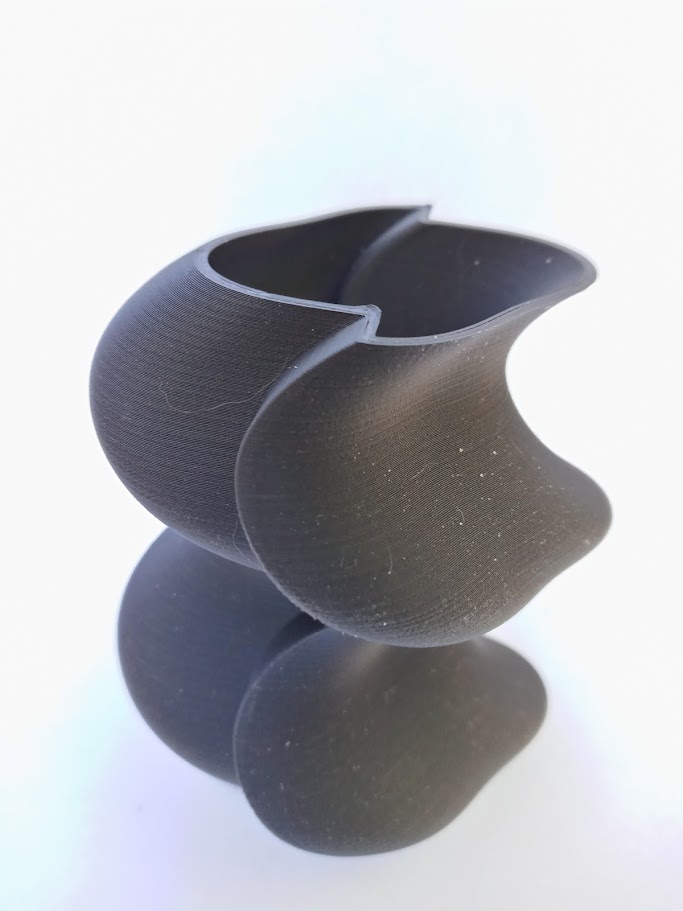
After figuring out the creative process, the rest was simply playing with parameters until I found designs that I liked. This process involved setting parameters for the sketches, then running a script to create the bottom and run the ExtrudeSurface function. I did not think ahead to record the parameters chosen, so the images below will only include the renderings of the chosen vessels.


Prints
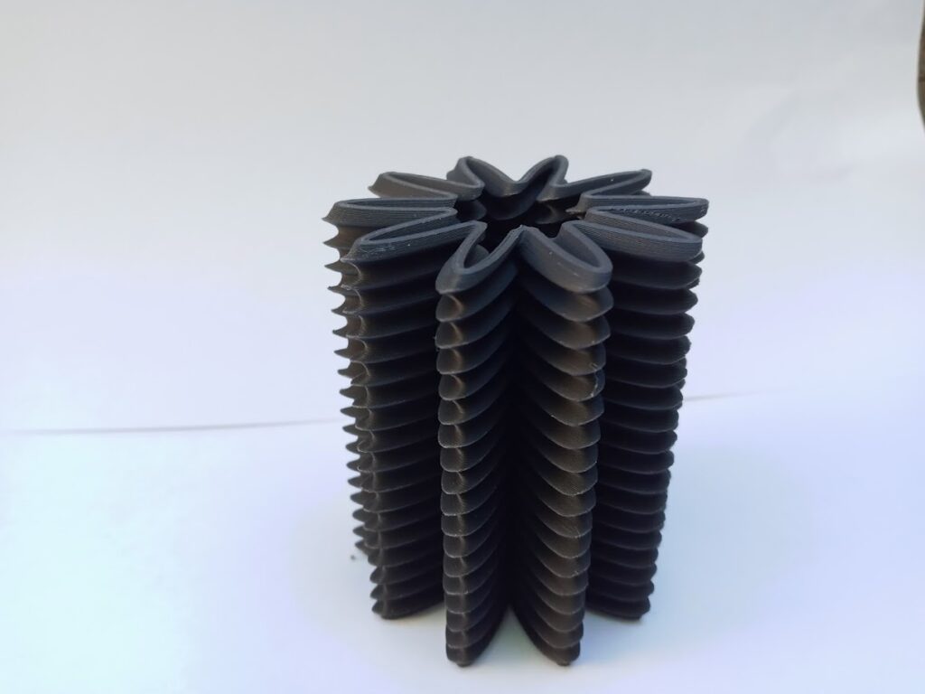
Here are the printed models displayed above. While it was earlier shown (and can be seen from playing with parameters) that increasingly exaggerated curves can be made by expanding the radius of the z-rail, I took a personal constraint in mind that all artifacts created should not require support structures during the printing process. This constraint caused a little concern when generating the toolpath for the first artifact posted above as it has the largest difference between the trough and peak of each loop, but I am proud to say that this turned out to be a non-issue. No issues occurred during the printing process for any of the artifacts.
Reflection
- From a design perspective, parametric design removes a limit of what you can think of reasonably making, which would be an issue with manual design in Rhino. For example, if I were to create the second artifact above traditionally, my immediate thought to make it in Rhino would have been to make 18 copies of the base curve, rotate each one then loft because the z-curve used as the rail would have been a pain to create traditionally.
- Repeating operations becomes trivial, reducing the time needed to create designs that would otherwise take a significant amount of time to create. Similarly, adjusting a shape or even making a new shape entirely is as simple as changing sets of parameters.
- Functions can now be saved and reused for future work. For example, if you were to know that you would need to create a bottom for an artifact, you can simply write a Python function to do such and employ that function whenever it is needed. In short, productivity is increased from the modularity that code provides.
One disadvantage to consider is that design from just using code can impact the ability to create non-conventional shapes. For example, consider creating a 3d model of a panda. How would you use code to create each object and determine its location? While possible, it may just be simpler to create the model solely in Rhino.
Hello Nathan! That was a creative idea to use the ExtrudeCrvAlongCrv command. I am surprised none of your designs required supports as there look to be some overhangs. Overall I like the final prints. I agree with your sense of authorship. There is still certainly ownership of the designs and the code but it is by its nature very repeatable.
Hey Elektra!
Thanks for the response. I was pretty surprised (and skeptical) about the lack of needed support structure as well. Each print definitely does have that distinct birthmark though (the small indented line going up the z-axis that shows where the toolpath moved to the next layer).
Hey Nathan, I really enjoyed your far left print. I like how smooth the curves are and the weird shape they create. I also thought your reflection was really insightful and totally agree that there are advantages and disadvantages to using parametric design. I had the same thoughts as use when thinking about how to recreate my vessels strictly in rhino and how it would be quite annoying and tedious to do, but I think your point about the panda is really good.
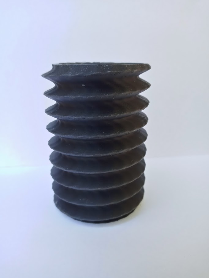
I loved the way the far-left print turned out too! It was definitely the artifact that I was most worried about when printing as it was my “let’s see if printing this is even feasible” print. Really though I personally find the far-right artifact the most interesting due to the very subtle trough in the base curve. Particularly, I found the printer being able to extrude a nearly precise copy of the rhino rendering for that artifact to be a testament to how accurate the toolpath is.