Minimizing Travel Paths in 3D Printing
Introduction
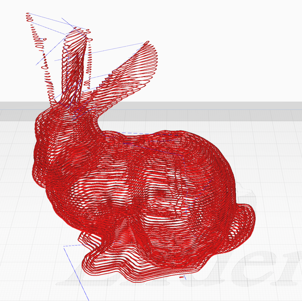
I started this project in the summer of 2023. Travel movements in 3D printing can cause messy prints, and even be the source of failures when the printing material is rheologically non-linear. Many of the materials developed in the Hand And Machine lab have unique properties that result in continuous extrusion, even when the machine has stopped printing. Taking this into consideration, I began working on this slicer that minimizes travel paths in both the xy-plane and in z in order to reduce travel motions in all three dimensions.
I tested the slicer on several different geometry types and will continue to do so in preparation for SIGGRAPH’s technical paper deadline in January. There are a few instances in which it fails which I discuss in the Future Work section, but overall it appears to be successful if slow. For each of these challenge areas I propose methods to improve the capability and efficiency of the slicer, and will be implementing them soon.
Background Research
There are several methods commonly used by slicers to generate the fill of a layer. However, these patterns do not require the printer head to follow a single path, and instead allow it to start and stop extruding in order to move the printer head to a new area. There are several space filling patterns that instead allow one to extrude continuously without travel movements such as the Hilbert and Peano curves, however they do not start and stop at the same location. Fermat spirals, as proposed by Zhao et. al. in their paper “Connected Fermat Spirals for Layered Fabrication” published in 2016, allow for a space filling toolpath that starts and stops at the same location (separated by only the printer extrusion width), completely eliminating travel paths for a single region.
Vertical toolpath minimization in 3D printing is a much more recent development. Kaplan et. al. introduced the idea of nozzle modification in traditional FDM printers in order to print vertically branching 3D models more cleanly and efficiently at the Symposium of Computational Fabrication in Seattle, WA in 2022. Their algorithm and hardware modification allows them to print multiple layers of a given section of a model before moving on to the next section, resulting in non-xy-planar travel movements in the z-direction provided the movement does not result in collisions with previously printed parts of the model.
Process
The majority of my time working on this project was spent developing the slicer code, and can be broken up into two loosely connected search problems: vertical travel path reduction and fermat spiraling of closed regions parallel to the xy-plane at each layer height. Technically either search problem can be conducted first, or parallel to one another, provided the starting point for spiraling the region is decided. This start point is used to measure weight between nodes in the vertical travel path reduction search.
Vertical Travel Path Reduction
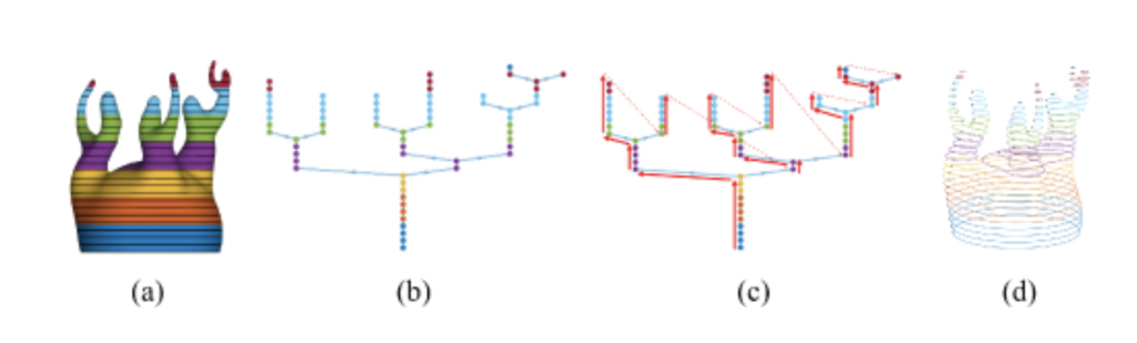
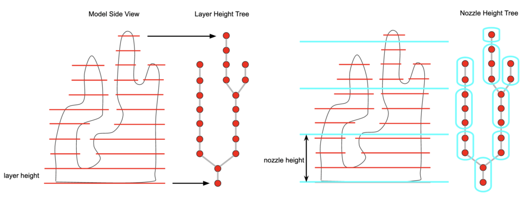
I start by creating a tree of the contours at a given layer height. I then divide this tree into “super nodes” grouped by nozzle height. Then, given a comparison of the sub nodes within each of these super nodes, I split if there is overlap between nodes in a given nozzle height chunk.
For every height chunk, I then create a directed weighted graph in which every node becomes a node in the graph, all parents have edges to their children, and all nodes have edges to their “siblings” and “cousins”, aka, nodes that are not direct descendants or ancestors. The weight of each edge is the distance between the start points of the nodes. I then perform a depth-first search to find a Hamiltonian path with the smallest weight for the fewest travel movements.
Graph Construction and Hamiltonian Path Video
Horizontal Travel Path Reduction
Given a slice of the model where it intersects with a plane parallel to the xy-plane at a given layer height, I group the nodes to create a collection of closed regions. For regions with holes, I create a graph in which every curve is a node and the edges are the shortest travel path between the curves. I find the minimum spanning tree between the nodes and then connect all the curves at those points in order to create a single outer contour.
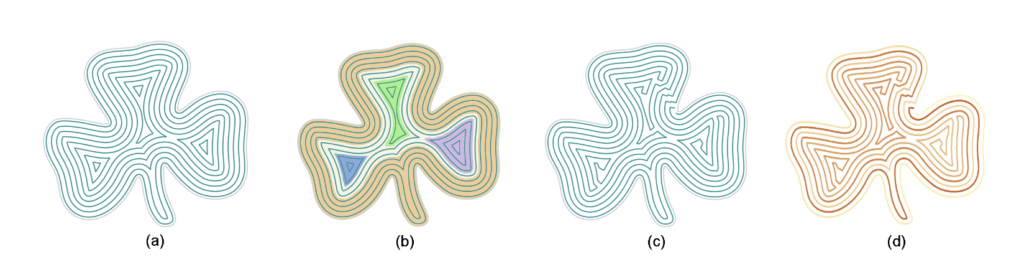
Fermat spiraling requires equidistant contouring of a given shape. Calculating these contours is a computationally difficult problem. Some slicers use pixel marching, which creates a bitmap in which each brightness value belongs to an isocontour, or isocontours in the case of multiple regions due to “pinching.” I used “point marching” instead, a process in which I divide the given curve into a number of evenly-spaced points equal to the length of the curve divided by the extrusion width and multiplied by some coefficient. I “march” these points inward by a vector orthogonal to the tangent at that point with a magnitude of the extrusion width. If all of these new points all maintain a distance greater than or equal to the extrusion width from the previous points, then they are kept. If they are less than the extrusion width from any previous point, they are removed and “pinching” occurs, which results in either isolated regions or fewer points due to a corner offsetting a point too close to the previous contour.
I spiral individual regions by finding points that are an extrusion width apart and connecting them to their next inner contour. This creates a single spiral in. Fermat spiraling involves finding a secondary “break” point an offset away from the previous, and marching inward to find an additional connection. The video below illustrates the process.
As the contours are generated, my algorithm creates a tree in which every subsequent contour is a child of the previous one. Nodes with more than one child become transition nodes. Groups of nodes with a single “local maxima” become spiralable regions. I connect every region to its parent contour in order to create a single path.
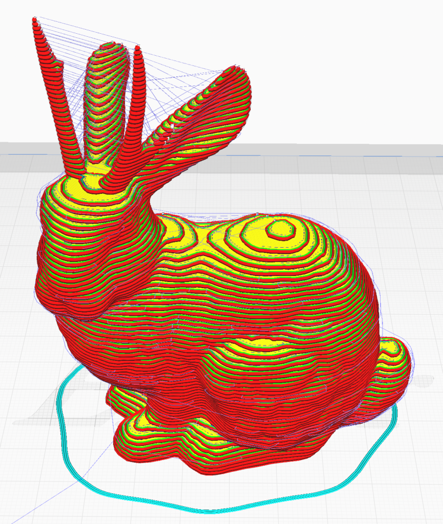
Putting all of these search problems together results in much fewer travel paths within the print directions.
I collaborated with several individuals in the lab to slice unique geometries for printing in various materials. Professor Buechley printed several pieces in CeraMetal, a material developed in the Hand And Machine lab composed of bronze powder and binding agents that can be printed with a typical desktop ceramic printer and fired to create a solid metal piece. Camilla Friedman-Gerlicz sliced and printed three unique solid shapes in a new printable glass material for her final project, which she elaborates on in her post. I also sliced and printed objects in both clay and ClayDough, another material developed in the Hand And Machine lab by Professor Buechley and Fiona Bell.
Outcome
Slicing Video / Printing Video
Future Work
The point marching algorithm is very slow. I plan on implementing pixel marching to significantly reduce the time spent generating the contours for the fermat spiraling. Hamiltonian path search is also slow. In a fully connected graph with n nodes, the time complexity of returning every single Hamiltonian path is O(n * n!). It is possible to implement dynamic programming to greatly reduce this, but with too many nodes the algorithm will still be computationally expensive. I will be looking into methods to combat this.
Reflection
I have learned a great deal about search problems, complexity, and had a great visual representation for understanding graph and tree search. I hope to eventually deploy this software so that other makers can use it, and to create many more artifacts with it myself.
Thank you!