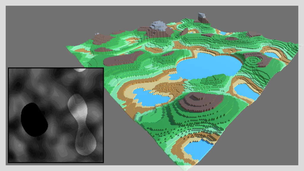
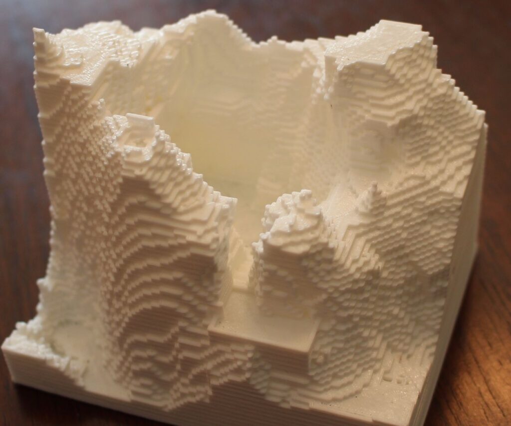
My project involves terrain generation with the goal of creating tiles that mimic the terrain generation in the game ‘Minecraft,’ while incorporating some vegetation elements. Although my initial intention was to closely emulate the ‘Minecraft’ theme, the final outcome took a different direction. However, I’m happy with the results.
I apologize for the videos not displaying correctly; they are in GIF format and cannot be played due to the lack of compatibility with video formats like .mp4.
Main Project Goal:
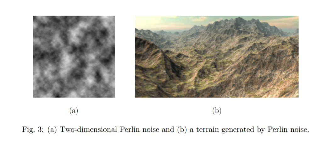
My project involves generating terrain tiles using Perlin noise for pseudo-random generation. I use quotes around ‘random’ because Perlin noise creates a pseudo-random appearance. Unlike true randomness, you can’t compute the same terrain twice with it. The key difference between using Perlin noise and a purely random function (often referred to as ‘white noise’) for terrain generation lies in the coherency and smoothness of the resulting terrain. While a purely random function might be simpler to implement for terrain generation, it generally yields less realistic and visually appealing results compared to Perlin noise. Perlin noise’s ability to create smooth, coherent variations makes it far superior for simulating the kinds of variations seen in natural terrains
The Idea
What Is Procedural Terrain Generation
Definition: Procedural terrain generation is an automated method using algorithms and randomness to create digital landscapes, avoiding manual design.
Significance: It’s essential for efficient and dynamic terrain creation in applications like gaming, simulations, and landscape design, saving time and resources.
Applications: Procedural terrain generation is used extensively in video games, simulations, and urban planning to generate diverse and realistic virtual terrains.
What is the Difference between Randomness(white noise) and Perlin Noise
The key difference between using Perlin noise and a purely random function (often called “white noise”) for terrain generation lies in the coherency and smoothness of the resulting output.
Perlin Noise:
- Smooth and Gradual Changes: Perlin noise generates values that change smoothly over space. Neighboring points in a Perlin noise field have similar values, which creates a natural-looking flow.
- Control Over Features: By adjusting parameters like frequency and amplitude, you can control the “roughness” or “smoothness” of the terrain, creating hills, valleys, and other features that have a consistent shape and size.
- Less Repetition: Perlin noise has a lower chance of producing identical values next to each other, which means the terrain won’t have a repeating pattern that is visibly grid-like.
- Natural Look: The noise is non-uniform and non-repetitive, which resembles natural phenomena, making it suitable for realistic terrain generation.
Pure Random Function:
- Abrupt Changes: A purely random function will generate a value for each point without regard for neighboring points. This results in a terrain with abrupt changes, lacking any form of smooth transitions.
- No Control Over Features: Pure randomness does not allow for easy control over terrain features. It is not straightforward to create rolling hills or gradual valleys as you can with Perlin noise.
- High Repetition: There is a higher chance of adjacent points having wildly different values, which can make the terrain look speckled or noisy and less like something you would find in nature.
- Unnatural Look: The noise is completely uniform and without any discernible pattern, which can be useful in some contexts but is typically not desirable for terrain, where you expect to see patterns like ridges, valleys, and other formations.
While a purely random function might be simpler to implement for terrain generation, it generally yields less realistic and visually appealing results compared to Perlin noise. Perlin noise’s ability to create smooth, coherent variations makes it far superior for simulating the kinds of variations seen in natural terrains.
How to Generate Perlin Noise
Perlin Noise the Algorithm
Perlin noise is a specific sequence of steps designed to produce a pattern of pseudo-random coherent noise, which can be used in computer graphics and other applications where natural-looking textures are needed.
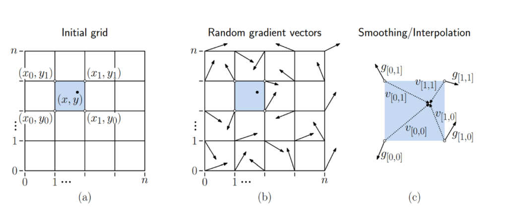
Fig. 1(a) – Initial Grid:
- Imagine a chessboard; this is your grid. Each square is part of this grid.
- The grid is made up of squares (like in graph paper) and has a certain number of squares along each side, denoted by “n”.
- Each intersection point on the grid, the corners of the squares, can be referenced by coordinates $(x_i, y_j)$
- The shaded square in the middle with a dot represents a particular square on the grid that we’re focusing on. The dot represents a point inside this square, which has specific coordinates \((x, y)\). $(x,y)$
Fig. 1(b) – Random Gradient Vectors:
- At each intersection point (corners of the squares), a random arrow (vector) is drawn. This arrow points in a random direction. These are the gradient vectors.
- The arrows don’t actually represent the direction of the terrain or texture but are used to influence the ‘randomness’ of the point within the square.
Fig. 1(c) – Smoothing/Interpolation:
- This figure shows how to smooth out the noise to avoid blocky patterns. For this, vectors from the corners of the square to the point of interest (the dot) are drawn, called “v”.
- The smoothing will consider the direction of the gradient vectors at the corners and the position of the point within the square.
General Process:
- Setup a Grid: You start with a grid (like graph paper) and have a grid point at each corner of the squares.
- Assign Random Gradients: At each grid point, you assign a random gradient vector (an arrow pointing in a random direction).
- Find the Square for Your Point: For any point where you want to know the noise (the shaded square with the dot), you find out which square of the grid it’s in and look at the corners of this square.
- Calculate Influence: You calculate how much each corner’s gradient vector should influence the point by using dot products. The dot product tells you if the point is moving with the gradient (uphill), against it (downhill), or neither (flat).
- Interpolate: You blend the influences of the four corners to get a smooth transition, so there are no sudden changes in the noise pattern.
- Add Variations: You can add variations at different scales (called octaves) to make the pattern more complex and natural-looking.
Perlin’s Technique: Ken Perlin came up with a smart way to make this randomness look natural by using gradients and a special smoothing function that makes sure the transitions between different noise values are smooth.
How did I use this in Rhyno?
The toughest part was figuring out how to generate Perlin noise values. So, I assumed someone had created a plugin for Rhino that deals with Perlin noise. To my expectations, there was one available! I installed the plugin and attempted to figure out how to use it and what each function does.
When I opened up the example file for the Perlin noise, it was definitely a challenge to figure out how to use this plugin.
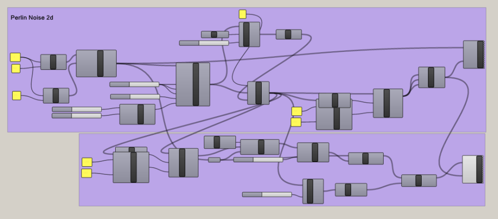
Rhyno Plugin for Perlin Noise
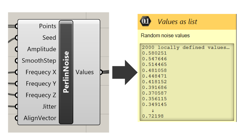
I luckily managed to figure out that I just needed to take one component from the extension and work with the rest. So here are the values that the Perlin noise component took in as input that I used to generate the Perlin noise values.
- Points: The input points where the noise value will be evaluated. The noise function will return different values based on the location of these points in space.
- Seed: A number that initializes the random number generator for the noise function. Changing the seed value will change the pattern of the noise, allowing for different noise textures while maintaining the same overall characteristics.
- Amplitude: The maximum value that the noise function can output. This controls the height or intensity of the noise. Higher amplitudes will result in more significant variations in the noise values.
- SmoothStep: A function that interpolates between two values. In the context of noise, it can be used to smooth out the transitions between noise values, resulting in a less abrupt change from point to point.
- Frequency X, Frequency Y, Frequency Z: These parameters control the frequency of the noise pattern along the respective axes. Higher frequency values will result in more rapid changes in the noise pattern, creating a more “zoomed in” effect, whereas lower frequencies will make the noise pattern appear more “zoomed out” or smooth.
- Jitter: This input might control the randomness added to the noise. Jitter can help to eliminate visible grid-like patterns in the noise by slightly perturbing the points before the noise calculation.
- AlignVector: This input likely adjusts the orientation of the noise pattern. By changing the align vector, you can rotate the direction of the noise gradients, which can be useful for aligning noise patterns to flow with certain geometries or directions.
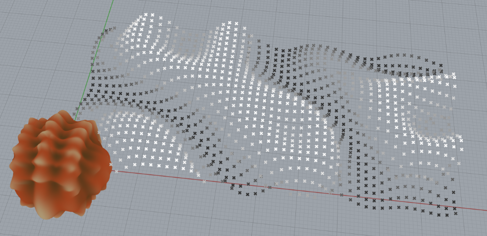
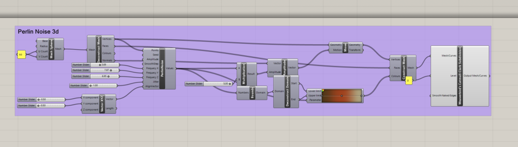
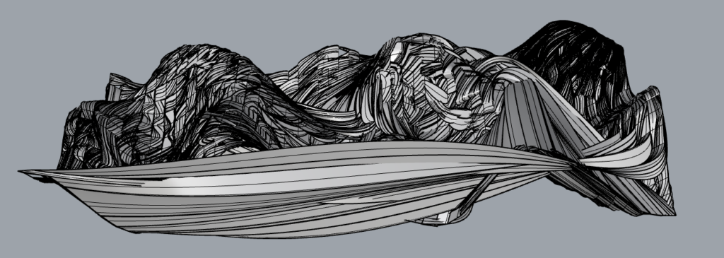
I needed to create python code to generate my grid and take in my Perlin noise values as my z variable for the height of my curves.
However, these are just grid lines, I couldn’t figure out how to create a surface from these grid lines. I tried joining the lines and then lofting them but it seemed some lines wanted to connect to other lines and the result was ugly.
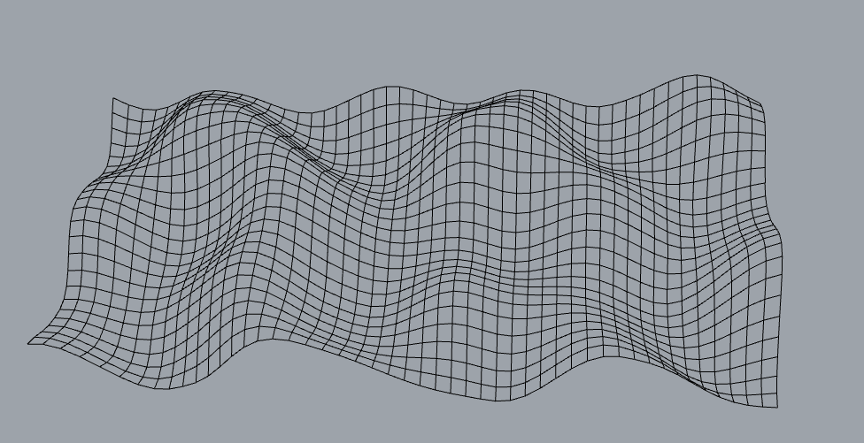
I then tried figuring out how to create a surface from the tools in Rhino, instead of trying to figure this out with code. So messing with the lofting tools, I stumbled on the patch. That thankfully worked for me!
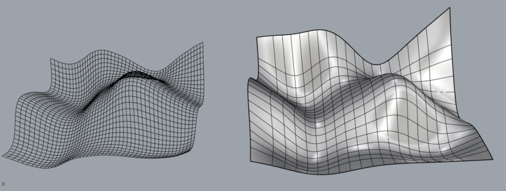
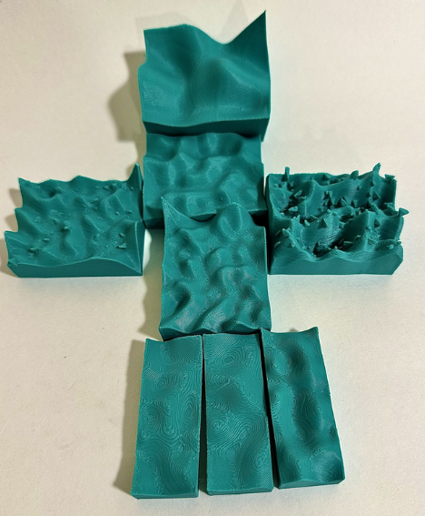
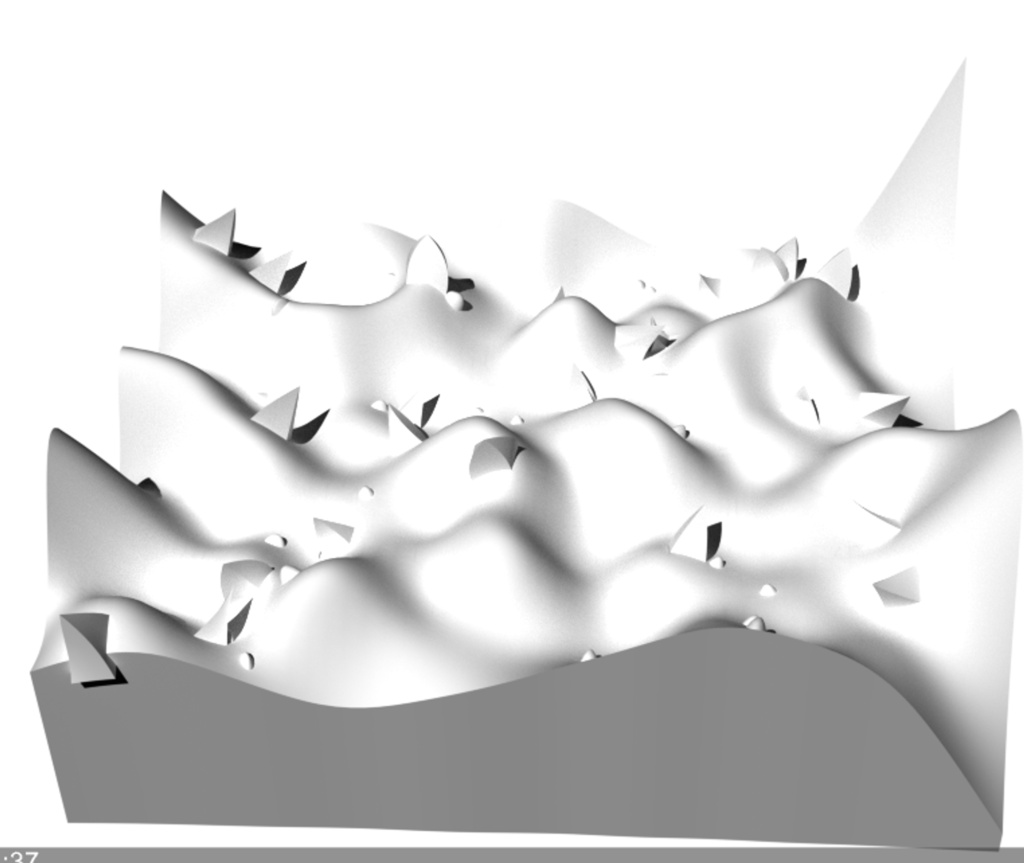
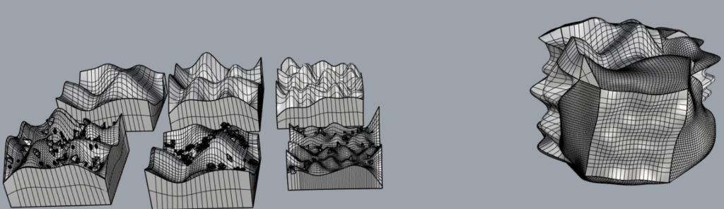
Here are a few results from the tiles I generated:
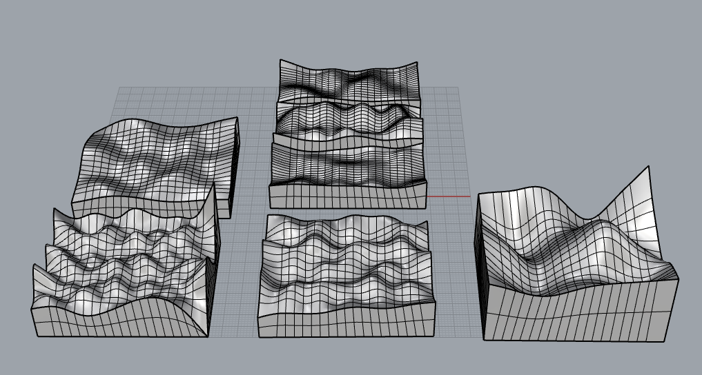
Although I wanted a more ‘pixelly’ look for the terrains, I really love how they turned out. My next goal is to figure out if I can create some grass and tree surfaces that I can attach to my terrain. I know that directly coding them onto the object would be difficult, as changing the slider parameters already makes the computation quite complex. Luckily, no crashes yet. So I’ll look into creating a flat surface with the grass, trees, etc., and then attaching them using methods like ‘Surface Along Curves’ to add the trees to the plane.
Zoom Effect
I call this a zoom effect but really I’m just messing with the parameters that control the frequency of the noise pattern along the respective axes. Higher frequency values will result in more rapid changes in the noise pattern, creating a more “zoomed in” effect, whereas lower frequencies will make the noise pattern appear more “zoomed out” or smooth. Again these videos won’t play, but I do have a link to my slides that will play.
Jitter/Randomness
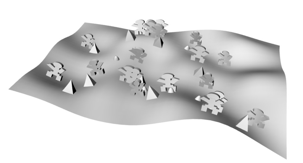
Vegetation Generation
I not only wanted a terrain surface but I also wanted some vegetation. So I created a square surface, and created code that generated n random pyramids and n random spheres for bushes. And got these results:
I then had to perform a surface morph to place this surface on top of my terrain surface.
I also wanted to create little people in my print but I knew they wouldn’t come out as great as I’d like given some printing complications that might occur.
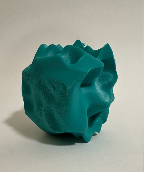
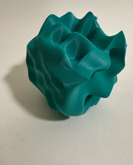
I successfully created my terrain tiles as planned. Additionally, I had the ambition to generate a globe-like representation of these surfaces, similar to the Earth. Initially, I attempted to apply surface morphing directly onto a sphere, but I encountered several complications along the way. As time was running out, I opted for a different approach. I divided my terrains into four sides and then joined them together. This decision led to the following results:
Final Prints