My project involves generating terrain tiles using Perlin noise for pseudo-random generation. I use quotes around ‘random’ because Perlin noise creates a pseudo-random appearance. Unlike true randomness, you can’t compute the same terrain twice with it. The key difference between using Perlin noise and a purely random function (often referred to as ‘white noise’) for terrain generation lies in the coherency and smoothness of the resulting terrain. While a purely random function might be simpler to implement for terrain generation, it generally yields less realistic and visually appealing results compared to Perlin noise. Perlin noise’s ability to create smooth, coherent variations makes it far superior for simulating the kinds of variations seen in natural terrains
The toughest part was figuring out how to generate Perlin noise values. So, I assumed someone had created a plugin for Rhino that deals with Perlin noise. To my expectations, there was one available! I installed the plugin and attempted to figure out how to use it and what each function does.
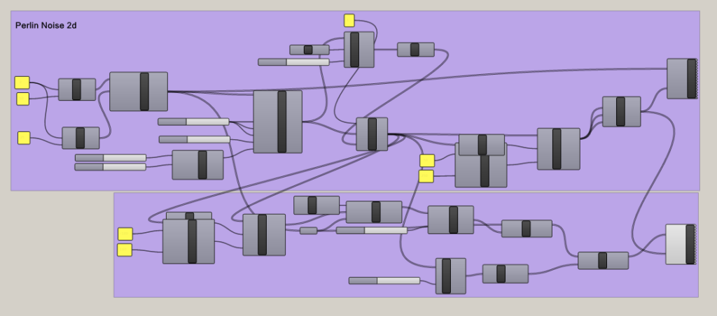
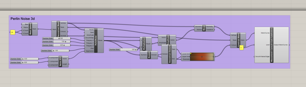
When I opened up the example file for the Perlin noise, it was definitely a challenge to figure out how to use this plugin.
I did figure out that the main Perlin Noise component is this one here, which is the only component I messed with:
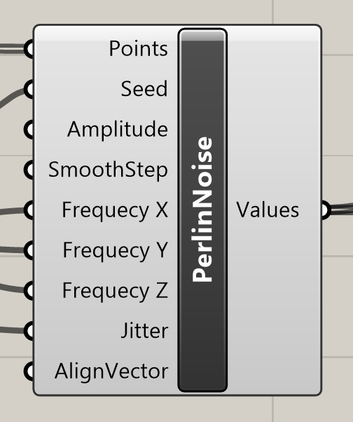
The Following are the Input definitions:
- Points: The input points where the noise value will be evaluated. The noise function will return different values based on the location of these points in space.
- Seed: A number that initializes the random number generator for the noise function. Changing the seed value will change the pattern of the noise, allowing for different noise textures while maintaining the same overall characteristics.
- Amplitude: The maximum value that the noise function can output. This controls the height or intensity of the noise. Higher amplitudes will result in more significant variations in the noise values.
- SmoothStep: A function that interpolates between two values. In the context of noise, it can be used to smooth out the transitions between noise values, resulting in a less abrupt change from point to point.
- Frequency X, Frequency Y, Frequency Z: These parameters control the frequency of the noise pattern along the respective axes. Higher frequency values will result in more rapid changes in the noise pattern, creating a more “zoomed in” effect, whereas lower frequencies will make the noise pattern appear more “zoomed out” or smooth.
- Jitter: This input might control the randomness added to the noise. Jitter can help to eliminate visible grid-like patterns in the noise by slightly perturbing the points before the noise calculation.
- AlignVector: This input likely adjusts the orientation of the noise pattern. By changing the align vector, you can rotate the direction of the noise gradients, which can be useful for aligning noise patterns to flow with certain geometries or directions.
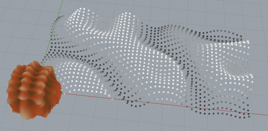
With this in mind, I was able to get some Perlin noise values. These types of values reminded me of when we went over bitmaps in class, where we had brightness values to create a topology. So, I looked back on those slides to help me create a solid for my noise values.
I did manage to create the grid pattern of my terrain.
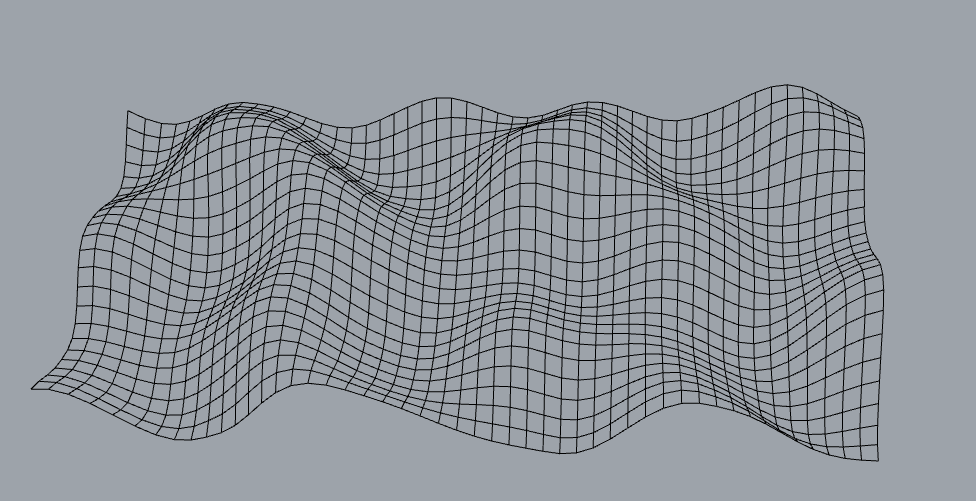
However, these are just grid lines, I couldn’t figure out how to create a surface from these grid lines. I tried joining the lines and then lofting them but it seemed some lines wanted to connect to other lines and the result was ugly.
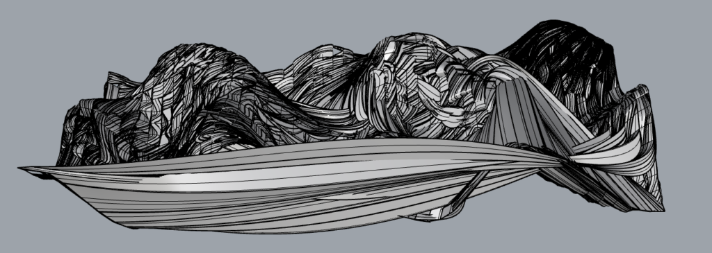
I then tried figuring out how to create a surface from the tools in Rhino, instead of trying to figure this out with code. So messing with the lofting tools, I stumbled on the patch. So I joined the lines and then patched them. They patched, but it was too small and “cramped” together. So I stretched it and got these results:
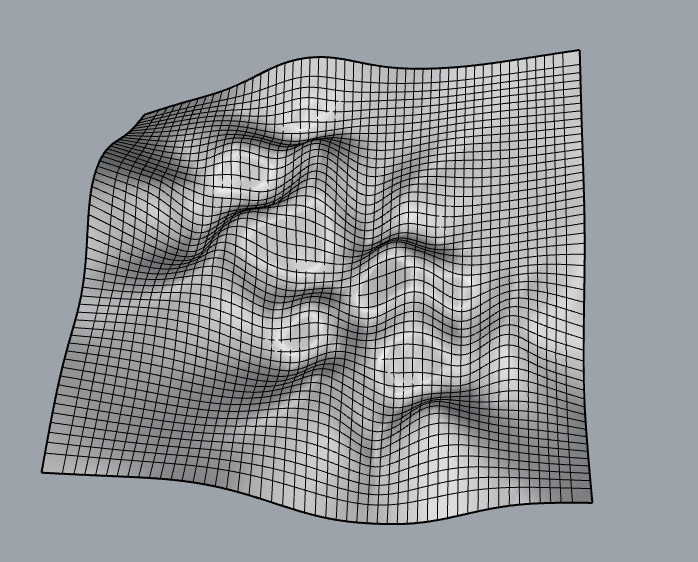
I then continued to follow along with the class slides for the bitmap. I was able to create surfaces, but as I tried to export them, I realized that the STL files were around 30MB! Typically, these STL files are only 1-5 MB in size. So, I knew something was wrong because even the G-code file was huge when I attempted slicing. I then discovered that my objects were excessively large in Rhino…
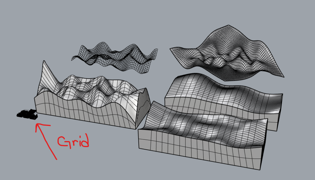
So I created a scale factor for my objects in Grasshopper. These are my final results in Rhyno
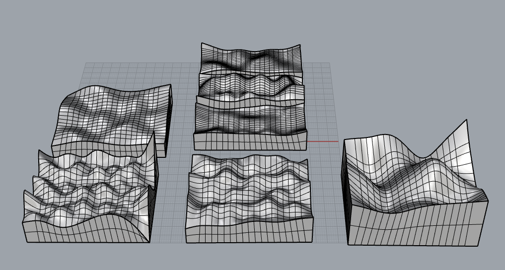
Although I wanted a more ‘pixelly’ look for the terrains, I really love how they turned out. My next goal is to figure out if I can create some grass and tree surfaces that I can attach to my terrain. I know that directly coding them onto the object would be difficult, as changing the slider parameters already makes the computation quite complex. Luckily, no crashes yet. So I’ll look into creating a flat surface with the grass, trees, etc., and then attaching them using methods like ‘Surface Along Curves’ to add the trees to the plane.
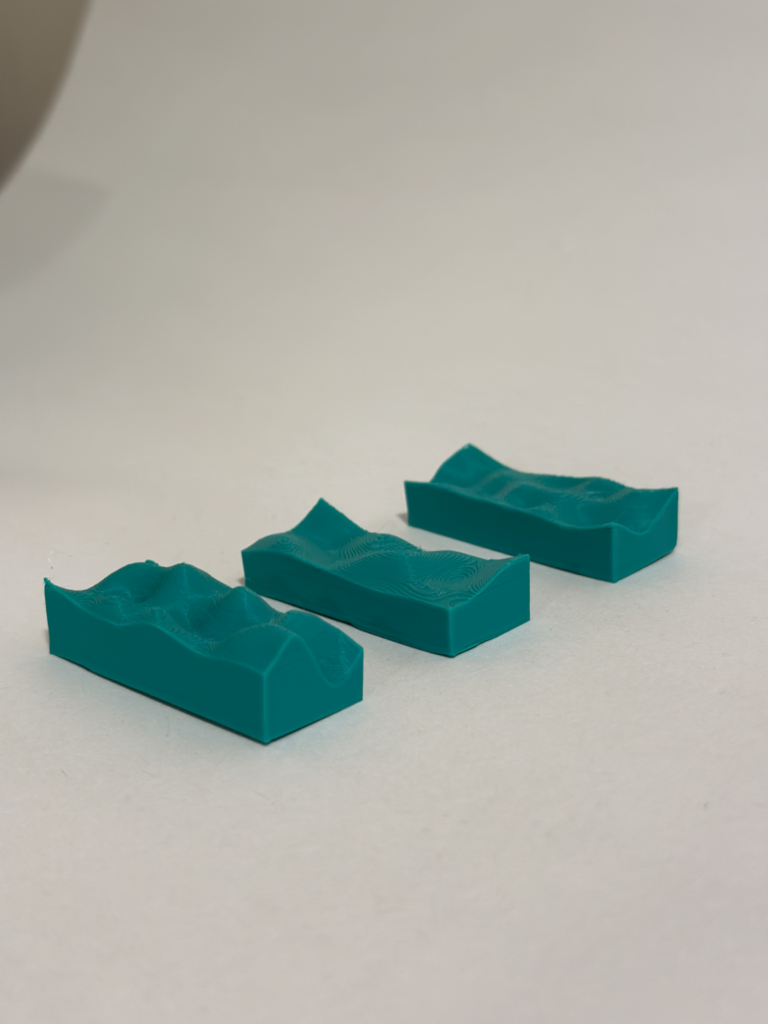
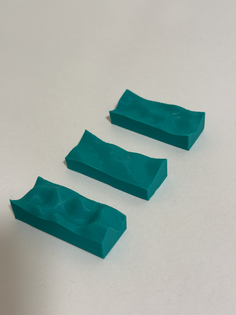
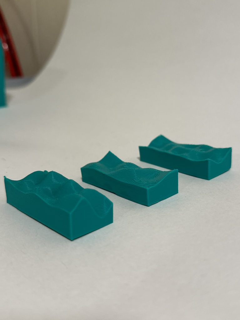
Finally, here are some trial prints I managed to create! Although, the images can’t really capture the curvature of the tiles. I really love how different the three of them look. I do wish there was a way to transition the three into one without the complexity involved. Although I do think I can accomplish this with a union in Rhino.
Timeline
November 1: Develop and fine-tune the procedural terrain generation script using Perlin noise.November 15: Create 3D models of Minecraft biomes, integrating the generated terrain features in Rhyno
Unfinished Goals/Tasks
- November 29: 3D print sample blocks for testing and validation.
- December 3: Paint the 3D blocks add details etc.
- December 4: Document the biome generation process and create the 10x10cm blocks.
- December 5: Finalize the project, make any necessary adjustments, and prepare for presentation.
Hey Nathaniel,
Really great job on your progress, in my experience the hardest part of random generation is to get it generating, everything after is about fitting the “glove” (the biome) on the “hand” (the noise). I noticed that you said you wish it turned out more blocky. I’m unaware of the inner workings, but if you can, you may be able to parse through the noise cells, check it’s Z height, and just build a cube shape that goes from that height down to 0. Just a thought though, but I think your next steps look good!